Supercharge Your Innovation With Domain-Expert AI Agents!

Connector

A connector and thread technology, applied in the field of connectors, can solve the problems of flange member removal, time-consuming, etc.

Active Publication Date: 2022-04-08
TECNA DISPLAY LTD
View PDF8 Cites 0 Cited by
  • Summary
  • Abstract
  • Description
  • Claims
  • Application Information

AI Technical Summary

Problems solved by technology

[0005] Although effective for releasably securing the support bracket to the beam, it has been observed that over-rotating the knob to release the bracket from the beam may result in the shaft of the flange member being removed from the knob
This requires reassembly of the support bracket which can be time consuming

Method used


Image

  • Connector
  • Connector
  • Connector

Examples


Embodiment Construction

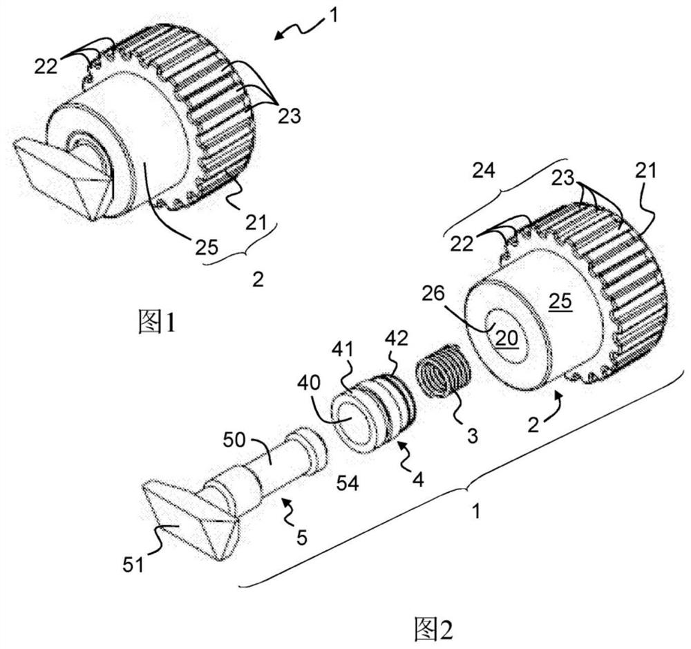
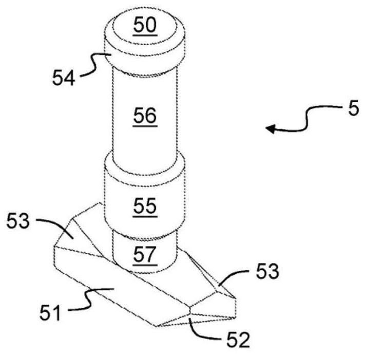
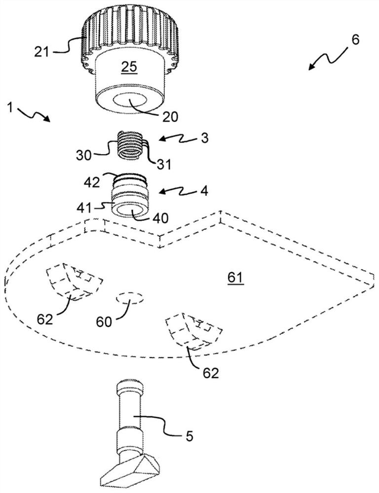
[0041] now refer to Figure 1 to Figure 3 , shows a connector 1 according to an embodiment of the present invention for releasably engaging a support member 11 (eg Figure 8 Shown in the slot 10 in). The connector 1 comprises a body 2 having a blind hole 20 in which a retaining element 3 , a threaded insert 4 and a bolt 5 are received.

[0042] The body 2 is in the form of a knob 2 in this embodiment and includes a grip portion 21 that is substantially cylindrical and includes a plurality of axial ribs 22 extending along the outer peripheral surface of the grip portion 21 and a plurality of The groove 23 , the plurality of axial ribs 22 and the plurality of grooves 23 together form a gripping surface 24 . The body 2 also includes a stem portion 25 which is also substantially cylindrical and has a smaller diameter than the grip portion 21 . The rod portion 25 is coaxial with the grip portion 21 and extends from one of the ends of the grip portion 21 . The blind hole 20 has ...


PUM


Abstract

A connector (1) for releasably engaging a slot (10) in a support member (11). The connector (1) comprises a body (2) having a blind hole (20) in which is received a retaining element (3), a threaded insert (4) and a shaft (50) bolts (5). The threaded insert (4) provides a threaded hole (40) that receives the shaft (50). The bolt (5) has a head (51) at the first end of the shaft (50), and the retaining element (3) is fixed to the second end of the shaft (50) to restrain the shaft (50) from the body (2 ) removed. The shaft (5) has a central threaded portion (55) between the head (51) and the retaining element (3) for engaging the threaded hole (40) such that the body (2) is positioned relative to the bolt The rotation of (5) pulls the head (51) towards the body (2) to capture and clamp the overhang (13) of the slot (10) in the support member (11) between the head (51) and the body (2) Between.

Description

technical field [0001] The present invention relates generally to connectors and more particularly to connectors for frames and the like. More specifically, the present invention relates to connectors and brackets for releasably engaging slots in support members of a frame or frame system. The connector and the bracket may form part of such a frame formed of support members, such as beams joined together to form a three-dimensional shape, to which beams the display panel is secured. Background technique [0002] Connectors and brackets for engaging slots in formed support members are known. One application of these connectors is a display frame of the type formed by a plurality of beams joined together to form a three-dimensional shape to which a display panel is secured. Display frames of this type are known to include multi-way nodefitting to provide a modular assembly that is easy to assemble and disassemble. One such display system is described in WO2008062161 by the ...

Claims


Application Information

Patent Timeline
Patent Type & Authority Patents(China)
IPC IPC(8): F16B7/18F16B37/04F16B41/00
CPCF16B7/187F16B37/045F16B37/122F16B41/002G09F15/0062F16B7/18
Inventor 乔纳森·埃维特
Owner TECNA DISPLAY LTD
Features
  • R&D
  • Intellectual Property
  • Life Sciences
  • Materials
  • Tech Scout
  • Unparalleled Data Quality
  • Higher Quality Content
  • 60% Fewer Hallucinations
Learn More