Message synchronization method and device
A message synchronization and message technology, applied in the field of communication, can solve problems such as data message forwarding failure, business cannot run normally, etc.
Active Publication Date: 2021-08-20
HUAWEI TECH CO LTD
0 Cites 0 Cited by
AI-Extracted Technical Summary
Problems solved by technology
[0005] The embodiment of the present application provides a message synchronization method and device to solve ...
Method used
[0096] In this embodiment, both the first PE and the second PE are connected to the CE, and the link between the first PE or the second PE and the CE not on...
Abstract
The present application provides a message synchronization method and device, the method comprising: the first service provider edge router PE receives the first message sent by the customer edge equipment CE; the first PE adds the Ethernet The network segment identifier ESI obtains the second message; the ESI is the ESI corresponding to the access port of the first PE; The virtual link tunnel corresponding to the ESI; the first PE sends the second message to the second PE through the virtual link tunnel, and the second message is used to instruct the second PE to send the The CE sends a data packet, and both the first PE and the second PE are connected to the CE. The message synchronization method provided by this application can ensure the correct forwarding of data messages, thereby ensuring the normal operation of services in the network.
Application Domain
Data switching networks
Technology Topic
RouterService provider +9
Image
Examples
- Experimental program(1)
Example Embodiment
[0066] Hereinafter, some terms in the present application will be explained to facilitate the understanding of those skilled in the art.
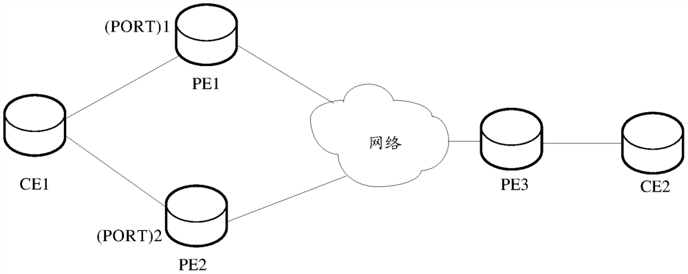
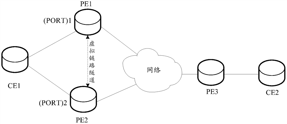
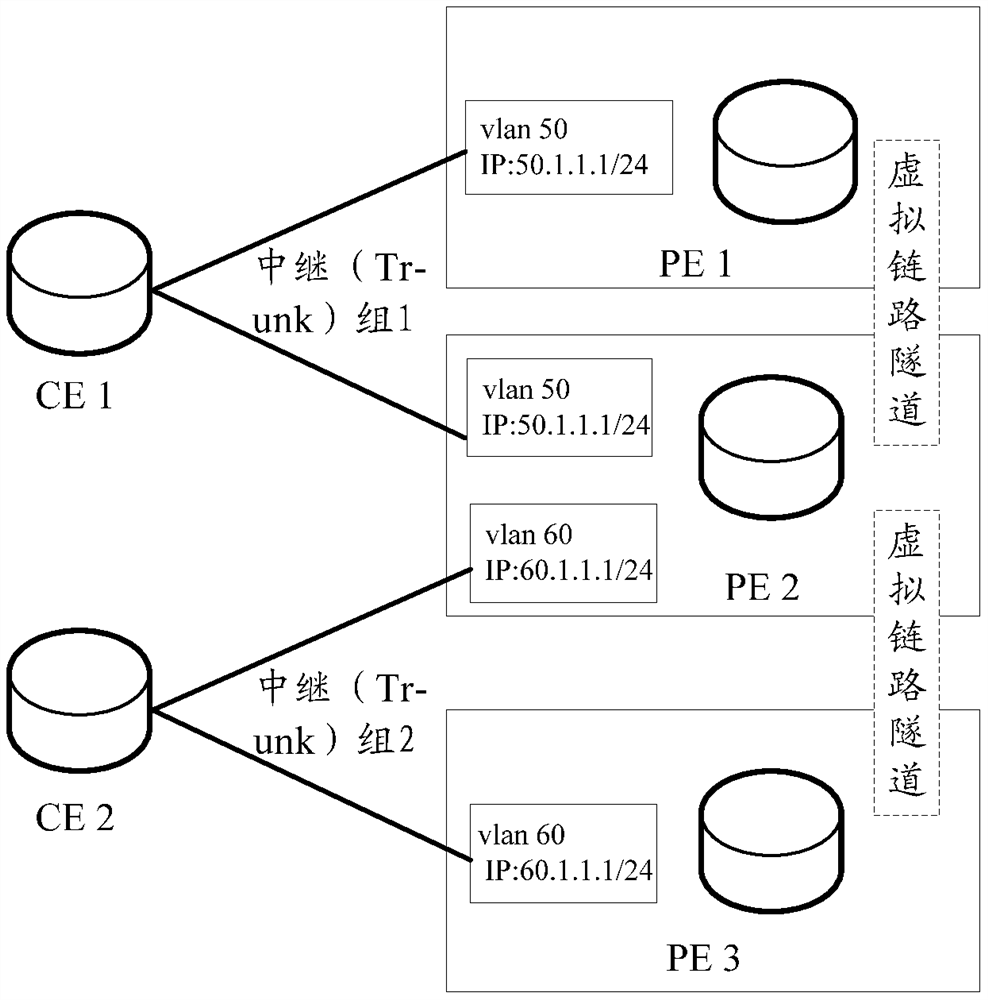
[0067] 1) Multi-home networking, which is an emergency disaster relief mechanism that can provide normal communication in time when sudden disaster accidents. The multi-belonging function is a CE that can be at the same time to a plurality of different PEs. When one of the PEs fail, the business of the CE can also be forwarded by other PE.
[0068] 2) The unit in this application refers to a functional unit or a logic unit. It can be implemented for software, and can implement its functionality by processor; or hardware form.
[0069] 3) "Multiple" refers to two or more, other quantifiers and the like. "And / or" describes the association relationship of the associated object, indicating that there are three relationships, such as A, / or B, which can be represented: Alone A, while there are three situations of B, alone. Character "/" generally means that the associated object is a "or" relationship. The ranges described in "above" or "following" include boundary points.
[0070] The packet synchronization method provided in the present application embodiment can be applied to multi-home networking, figure 2 The use scenario showing the use of the packet synchronization method provided in the present application embodiment, such as figure 2 As shown, CE1, CE2, PE1, PE2, and PE3, wherein CE1 is connected by port (port) 1 and PE2, and PE1 and PE2 are connected through the network. Such as wide area networks) are connected to PE3, PE3 and CE2 are connected, and there is a virtual link tunnel between PE1 and PE2 to perform packets between PE1 and PE2, PE1 and PE2 configuration of the same user-side virtual local area network (VirtualLocal Area) Network, VLAN) and interface IP. Follow the Ethernet VirtualPrivate Network (EVPN) standard, the same ESI is assigned to the port of PE1 and PE2 dual-return access.
[0071] Refer figure 2 When CE2 forwards data packets to CE1, there will be two forwarding paths, which are CE2-> PE3-> PE1 -> (port) 1-> CE1 and CE2-> PE3-> PE2-> (port) 2-> CE1, the same, CE1 also has two forwarding paths to CE2 forwarding data packets, which are CE1-> (port) 1-> PE1-> PE3-> CE2 and CE1 -> (port) 2-> PE2- > PE3-> CE2.
[0072] When CE1 forwards the data packet to the CE2, CE1 randomly selects a path from the two paths to CE2, when the CE2 forwards the data packet to the CE1, CE2 sends the data packet to PE3, PE3 randomly selects a path from the foregoing two paths to CE1 forwarding the data packet, PE1 or PE2, after receiving the data packet, forwarding the data packets to CE1 according to the local ARP to find the corresponding port. When the uplink data packet sent from the CE1 to the CE2 is only PE1, there is no ARP to CE1 in PE2. At this time, if PE3 is forwarded to the CE1 to the CE1, PE2 will send an ARP request message to all CE1 connected to it, because the ARP request carries a destination network protocol with data packets (Internet Protocol, IP) address Therefore, when the CE1 receives the ARP request message, and determines that the IP address carried in the ARP request message is, the message will be sent. Since there is two paths of the CE1 send packets, if the CE1 transmits packets via PE1, the packets sent by CE1 will not be received, and therefore, PE3 forwards data packets to CE1 through PE2 will fail. Leading the business in the network cannot run normally.
[0073] The embodiment of this application takes into account these situations. figure 2 Based on the system architecture shown, a packet synchronization method is proposed. In this method, the PE1 adds the Ethernet segment corresponding to the access port of the PE1 in the first message to the first message. Ethernet Segment Identifier, ESI) obtains the second message, and determines the virtual link tunnel corresponding to the ESI to determine the virtual link tunnel according to the correspondence between the ESI and the virtual link tunnel. After determining the virtual link tunnel, PE1 passes The virtual link tunnel transmits the second message to the PE2, and PE2 transmits data packets according to the second message to CE1, since there is a virtual link tunnel between PE1 and PE2, PE1 and PE2 can pass the virtual link. The tunnel is synchronized by the tunnel, so regardless of the CE1 sends the packet to PE1 or PE2, it can guarantee the correct transmission of the data packets, thereby ensuring the normal operation of the business in the network.
[0074] in addition, image 3 Schematic of CE multi-belonging network, such as image 3 As shown, CE 1 is returned to PE 1 and PE 2, and CE 2 is returned to PE 2 and PE 3, and a B-type protection (Typeb) is configured on the CE 1 and CE 2, and the Typeb). (TRUNK) Group, PE 1 and PE 2 are configured the same user-side VLAN and interface IP, such as VLAN 50 and IP: 50.1.1.1/24, ie PE 1 and PE 2 pair CE 1 virtual into one PE, PE 2 and PE 3 configuration The user side VLAN and interface IP, such as VLAN 60 and IP: 60.1.1.1/24, ie PE 2 and PE 3 pair CE 2 virtual into a PE. There is a virtual link tunnel between PE 1 and PE 2, and there is a virtual link tunnel between PE2 and PE 3, so that PE 1 and PE 2 can achieve synchronization of packets, PE 2 and PE, between PE 1 and PE 2. 3 can also achieve synchronization of packets through a virtual link tunnel.
[0075] In addition, if image 3 As shown, since the virtual link tunnel is present between PE 1 and PE 2, there is also a virtual link tunnel between PE 2 and PE 3, and the PE 2 will have two ESI corresponding to the access port, so PE2 is When packet forwarding, you can determine which virtual link tunnels are forwarded through which virtual link tunnel can be forwarded through the correspondence between ESI and virtual link tunnel.
[0076]It should be noted that in the present application embodiment, the communication synchronization method in the multi-belonging network is similar to the method of packet synchronization in the dual-home network, and details are not described herein.
[0077] The technical solutions of the present application and how the technical solutions in the present application will be described in detail below with specific embodiments. The following specific embodiments can be combined with each other, and will not be described in some embodiments for the same or similar concepts or processes. The embodiment of the present application will be described below with reference to the drawings.
[0078] Figure 4 The signaling flow chart of the embodiment of the present application message synchronization method. In the above figure 2 On the basis of the system architecture, such as Figure 4 As shown, the method of this embodiment can include:
[0079] Step 401, the first PE receives the first message sent by the CE.
[0080] In this embodiment, the first message can be control packets, protocol messages, or business packets, where business packets are, for example, ARP, Dynamic Host Configuration Protocol, DHCP, or Internet Management Protocol (Internet Group Management Protocol, IGMP), etc. Of course, the first message can also be other packets, for the specific form of the first message, this embodiment does not limit this.
[0081] When the first PE and the second PE can perform real-time synchronization when the packet is synchronized, it can also be batch synchronization.
[0082] Specifically, when the packets of the first PE and the second PE need to be synchronized in real time, the first PE will trigger the synchronization of the packet after receiving the first message sent by the CE.
[0083] In addition, the second PE may not exist because the first PE is newly added / TRUNK group member. When the first PE is received, the second PE may not exist because the first PE is received by the first message transmitted by the CE. When the second PE is working normally, the first PE has ended receiving the first message, at which point, the first PE and the second PE will not be able to perform the real-time synchronization of the packets, but to perform bulk synchronization. In a possible implementation, when the second PE is working normally, the second PE sends a request message to the first PE, wherein the request message includes the ESI corresponding to the access port corresponding to the second PE, the first PE Depending on the received request message, the first message will be acquired locally, where the first message includes information of all the users corresponding to the ESI. Further, after the first PE receives the packet sent by the CE, the user information is generated by the packet, and when the first PE is received, after the request message sent by the second PE, the access port of the first PE will be learned from the local. All user information corresponding to the corresponding ESI, and the learned user information is packaged as the first message. It is desirable that the ESI corresponds to the ESI corresponding to the access port corresponding to the first PE, and therefore, the first PE can correspond to the ESI corresponding to the access port of the second PE in the request message. , Obtain the first message corresponding to the ESI corresponding to the access port of the first PE.
[0084] Step 402, the first PE adds ESI to the first message to obtain the second message.
[0085] Wherein, the ESI is an ESI corresponding to the access port of the first PE.
[0086] In the present embodiment, after the first PE is acquired, the ESI corresponding to the access port corresponding to the first PE is added to the first packet, and obtain the second message.
[0087] In a possible implementation, the first PE can add an ESI in the packet head of the first message, or the addition of ESI at the end of the first message, of course, can also be in the first message Add ESI to add ESI, for the specific manner added, this embodiment does not limit this.
[0088] Step 403, the first PE determines the virtual link tunnel corresponding to the ESI according to the correspondence between the ESI and the virtual link tunnel.
[0089] In the present embodiment, a bit-point virtual link tunnel is established between the first PE and the second PE such that there is no direct link connection between the first PE and the second PE.
[0090] Among them, the virtual link tunnel between the first PE and the second PE includes a virtual extension LAN, VXLAN Tunnel, a multi-protocol label switch (MPLS) virtual line service (Virtual Private Wire Service, VWPS) Tunnel or generic routing encapsulation, greet tunnel, etc. Among them, when the virtual link tunnel is the MPLS VWPS tunnel, the convergence network in the dual homing network is the MPLS network. When the virtual link tunnel is the GRE tunnel, the bisquisch network is a network of convergence networks for IP networks.
[0091] In one possible embodiment, the first PE determines the ESI and the virtual link tunnel before determining the virtual link tunnel corresponding to the ESI, according to the correspondence between the ESI and the virtual link tunnel. The correspondence. Specifically, the first PE first establishes a virtual link tunnel between the first PE and the second PE. After the completion is established, the correspondence between the ESI and the virtual link tunnel will be established, of which the ESI is the first, respectively. The access port of the PE and the access port of the second PE are allocated, since the first PE and the second PE are connected to the CE connection, the access port of the first PE and the second PE access port will be used. Port assign the same ESI.
[0092] It is worth noting that if the first PE or second PE connection is connected to a plurality of CEs, a virtual link tunnel can be established independently for each ESI, that is, each ESI corresponds to different virtual. The link tunnel can also be multiplexed with the same virtual link tunnel, i.e., there is only one virtual link tunnel between the first PE and the second PE, and a plurality of ESI correspond to the same virtual link tunnel.
[0093] Further, it will be appreciated that the order of the above steps 402 and step 403 is merely illustrative. Step 402 is distinguished from the order of the order in which step 403 is not performed, and step 402 can be performed before performing step 403; or step 403 can be performed first, then perform step 402; can also perform the two steps simultaneously, the present application example pair This is not particularly limited.
[0094] Step 404, the first PE sends a second message to the second PE through a virtual link tunnel.
[0095] Wherein, the second packet is used to indicate the second PE to the CE transmission data packet, the first PE and the second PE are connected to the CE.
[0096] In the present embodiment, the first PE and the second PE are connected to the CE, and the first PE or second PE is connected to the CE, which not only supports Ethernet Ethernet access, but also supports passive optical network (Passive Optical) Network, pon) Access, thereby improving the flexibility of access.
[0097] The first PE determines the virtual link tunnel corresponding to the ESI, and sends a second packet to the second PE after the virtual link tunnel corresponding to the ESI is transmitted according to its own access port. After receiving the second message, the second PE will send data packets from the second message to CE. Further, the second packet is used not only to indicate the second PE to the CE to send data packets, but also to indicate that the second PE is related to the CE information for access security, and other services related to the user CE.
[0098] Step 405, the second PE parsed the second message to obtain the first packets and ESI.
[0099] In the present embodiment, the second PE will parse the second message and obtain the first packets and ESI after receiving the second packet sent by the first PE.
[0100] Step 406, the second PE sends a data packet to the CE according to the first packets and ESI.
[0101] In the present embodiment, since the ESI of the first PE is the same as the ESI of the access port of the second PE, the second PE may obtain the access port information of the native according to the ESI obtained.
[0102] In one possible implementation, the first packet includes a Media AccessControl, MAC) address, and transmits the second packet to the second PE through the virtual link tunnel, second The PE restores the first packets and ESI, and after obtaining the MAC address of the CE of the first message, it will transmit data packets according to the machine's access port information and the aforementioned MAC address to the corresponding CE. Therefore, for the second PE, a message corresponding to the CE transmission is received directly, thereby ensuring the correct forwarding of the data packet.
[0103] In addition, the first packet may also include information that can uniquely identify the CE, and the present application embodiment is not limited thereto for the first packet included.
[0104] Further, after the synchronization of the message in the manner in this embodiment, although the CE only transmits a message, the first PE and the second PE can receive and process the packet simultaneously, so that the first PE and The second PE can maintain the software data entry of this unit.
[0105] It is to be described that the first PE and the second PE are equal, that is, the second PE can be added after the first message is acquired, and the access port corresponding to the second PE is added to the first message. ESI, and transmitted to the first PE by the virtual link tunnel to be added to the first PE by the virtual link tunnel to achieve a packet synchronization between the first PE and the second PE, based on the virtual link tunnel corresponding to the ESI.
[0106] The packet synchronization method provided in the present application, the first PE is added to the first message transmitted by the CE, and the second packet is added in the first message, where the ESI is the first PE. The ESI, the first PE corresponding to the corresponding relationship between the ESI and the virtual link tunnel, determines the virtual link tunnel corresponding to the ESI, and sends a second PE through the determined virtual link tunnel. Packets, so that the second PE sends data packets to the CE according to the second message. Since the virtual link tunnel of the point-to-point point is established between the first PE and the second PE, the first PE adds an ESI identifier to the first message to obtain a second message, through the virtual chain between the first PE and the second PE. The road tunnel sends the second packet to the second PE to make the second PE send the data packet to the CE, thereby ensuring the correct forwarding of the data packet, thereby ensuring the normal operation of the business in the network.
[0107] Figure 5 The signaling flow chart of the second example 2 of the present application packet synchronization method. In the above embodiments and figure 2 On the basis of the system architecture, the first message transmitted by the CE is received in the first PE, and the first message is the first ARP message as an example. like Figure 5 As shown, the method of this embodiment can include:
[0108] Step 501, the first PE receives the first ARP message sent by the CE.
[0109] In one possible embodiment, the first ARP message carries the MAC address information with CE, and the first ARP message is used to indicate the first PE or second PE to forward the data packet to the MAC address information. .
[0110] Step 502, the first PE adds the ESI corresponding to the ESI corresponding to the access port of the first PE in the first ARP message to obtain the second ARP message.
[0111] Step 503, the first PE determines the virtual link tunnel corresponding to the ESI according to the correspondence between the ESI and the virtual link tunnel.
[0112] Among them, the virtual link tunnel corresponding to the ESI is a point-to-point virtual link tunnel between the first PE and the second PE, such as a VXLAN tunnel, an MPLS tunnel or a GRE tunnel.
[0113] Step 504, the first PE sends a second ARP message to the second PE through the virtual link tunnel.
[0114] The first PE and the second PE are connected to the CE, and the second ARP message is used to indicate the second PE to send data packets to the CE.
[0115] Step 505, the second PE parsed the second ARP packet to obtain first ARP packets and ESI.
[0116] Step 506, the second PE sends data packets to the CE according to the first ARP packets and ESI.
[0117] The ESI corresponding to the access port of the first PE and the second PE is the same, and therefore, after obtaining the ESI, it will obtain the local access port information according to the ESI, and by resolving the first ARP message. , Get the MAC address carried in the first ARP packet, so that the second PE will send the data packet to the CE by access port information and the MAC address.
[0118] The packet synchronization method provided in this application embodiment, the first PE is added to the first message, and the second packet is obtained in the first message, wherein the ESI is the first PE access. The port corresponding to the ESI, the first PE determines the virtual link tunnel corresponding to the ESI according to the correspondence between the ESI and the virtual link tunnel, and sends a second packet to the second PE by determining the virtual link tunnel. A data packet is transmitted to the CE according to the second packet. Since the virtual link tunnel of the point-to-point point is established between the first PE and the second PE, the first PE adds an ESI identifier to the first message to obtain a second message, through the virtual chain between the first PE and the second PE. The road tunnel sends the second packet to the second PE to make the second PE send the data packet to the CE, thereby ensuring the correct forwarding of the data packet, thereby ensuring the normal operation of the business in the network.
[0119] Image 6 For example, a structural diagram of an embodiment of a packet synchronization device provided in the present application embodiment, see Image 6 The synchronization device includes: a receiving unit 11, a processing unit 12, a determining unit 13, and a transmitting unit 14, wherein:
[0120] The receiving unit 11 is used to receive the first newspaper sent by the user boundary device CE;
[0121] The processing unit 12 is configured to add an Ethernet segment identifier ESI to obtain a second packet in the first packet; the ESI is an ESI corresponding to the first PE.
[0122] The determining unit 13 is used to determine a virtual link tunnel corresponding to the ESI according to the correspondence between the ESI and the virtual link tunnel;
[0123] The transmitting unit 14 is configured to transmit the second packet to the second PE by the virtual link tunnel, the second message for indicating the second PE to send data packets to the user boundary device CE, the The first PE and the second PE are all connected to the CE.
[0124] The above apparatus can be used to perform the method provided by the above-described corresponding method embodiment, the specific implementation and technical effects are similar, and details are not described herein.
[0125] Alternatively, the receiving unit 11 is further configured to receive a request message transmitted by the second PE, the request message including an ESI corresponding to the second PE.
[0126] The above apparatus can be used to perform the method provided by the above-described corresponding method embodiment, the specific implementation and technical effects are similar, and details are not described herein.
[0127] Figure 7 For the schematic structural diagram of the second embodiment of the packet synchronization device provided in the present application embodiment, see Figure 7 ,exist Image 6 Based on the embodiment shown, the apparatus further includes: establishing a unit 15.
[0128] The establishment unit 15 is used to establish a virtual link tunnel between the first PE and the second PE;
[0129] The establishment unit 15 is also used to establish a correspondence between the ESI and the virtual link tunnel, the ESI being the CE, the first PE, the access port and the second PE Access port allocation.
[0130] Alternatively, the virtual link tunnel includes a virtual extension local area network VxLAN tunnel, a multi-protocol tag switched MPLS tunnel or a general routing package GRE tunnel.
[0131] The above apparatus can be used to perform the method provided by the above-described corresponding method embodiment, the specific implementation and technical effects are similar, and details are not described herein.
[0132] It should be noted that the division of each unit of the above message synchronization device should be understood is merely a partition of a logical function. When actually implementation, it can be integrated into a physical entity, or physically separate. Moreover, these units can be implemented in the form of software by software; can also be implemented in the form of hardware; it can also be implemented in the form of a processing element call by software, and partial units are implemented in the form of hardware. For example, the acquisition unit may be a separately set processing element, or an integrated in a single chip in the PE, in addition, in the memory of the PE in the memory of the PE, a one of the PE is called and executed Get the function of the unit. The realization of other units is similar. In addition, these units can be integrated or partially implemented independently. The processing unit described here may be an integrated circuit with a signal of signal. In the implementation process, the various steps or above of the above method may be completed by the integrated logic circuit or software form of hardware in the processor element.
[0133] The above units may be one or more integrated circuits configured to implement the above methods, such as one or more specific integrated circuits (Application Specific Integrated Circuit, ASIC), or, one or more microprocessors (DIGITAL SIGNAL Processor) , DSP, or, one or more field programmable gate arrays, FPGAs, and the like. Again, when an element is implemented by the form of a process element scheduler, the computing unit can be a general purpose processor, a central processor (CPU), or other processor that can call programs. For example, these units can be integrated together, implemented in the form of SYSTEM-ON-A-CHIP, SOC.
[0134] Figure 8 For example, the structure of the third embodiment of the packet synchronization device provided herein, see Figure 8 The synchronization device includes: receiving unit 21, parsing unit 22, and transmitting unit 23, wherein:
[0135] The receiving unit 21 is configured to receive a second packet transmitted by the first PE through a virtual link tunnel, the virtual link tunnel being a link corresponding to an Ethernet segment identifier ESI corresponding to the first PE. Tunnel, the second packet is a packet to which the first PE is received after the first packet transmitted by the user boundary device CE, the first PE and the second PE Connected to the CE;
[0136] The resolution unit 22 is used to parse the second packet to obtain the first message and the ESI;
[0137] The transmitting unit 23 is configured to send data packets to the CE according to the first packet and the ESI.
[0138] The above apparatus can be used to perform the method provided by the above-described corresponding method embodiment, the specific implementation and technical effects are similar, and details are not described herein.
[0139] Alternatively, the transmitting unit 23 is further configured to send a request message to the first PE, the request message including an ESI corresponding to the second PE, the request message for requesting the acquisition. All messages corresponding to ESI.
[0140] Alternatively, the virtual link tunnel includes a virtual extension local area network VxLAN tunnel, a multi-protocol tag switched MPLS tunnel or a general routing package GRE tunnel.
[0141] The above apparatus can be used to perform the method provided by the above-described corresponding method embodiment, the specific implementation and technical effects are similar, and details are not described herein.
[0142] It should be noted that the division of each unit of the above message synchronization device should be understood is merely a partition of a logical function. When actually implementation, it can be integrated into a physical entity, or physically separate. Moreover, these units can be implemented in the form of software by software; can also be implemented in the form of hardware; it can also be implemented in the form of a processing element call by software, and partial units are implemented in the form of hardware. For example, the receiving unit may be a separate processing element separately, and can be integrated into a single chip in the PE, in addition, in the form of a program in the form of the PE, a one of the PE is called and executed The function of the receiving unit. The realization of other units is similar. In addition, these units can be integrated or partially implemented independently. The parsing unit described here can be an integrated circuit with signal processing capability. In the implementation process, the various steps or above of the above method may be completed by the integrated logic circuit or software form of hardware in the processor element.
[0143] The above units may be one or more integrated circuits configured to implement the above methods, such as one or more specific integrated circuits (Application Specific Integrated Circuit, ASIC), or, one or more microprocessors (DIGITAL SIGNAL Processor) , DSP, or, one or more field programmable gate arrays, FPGAs, and the like. Again, when an element is implemented by the form of a process element scheduler, the computing unit can be a general purpose processor, a central processor (CPU), or other processor that can call programs. For example, these units can be integrated together, implemented in the form of SYSTEM-ON-A-CHIP, SOC.
[0144] Figure 9A A possible structural diagram of this application PE. See Figure 9AShown, the PE 100 comprises: a processing unit 102 and a communication unit 103. Processing unit 102 for controlling the operation of PE 100 performs management, for example, the processing unit 102 to PE 100 support the packet synchronization method perform the steps in the embodiments and / or other processes for the techniques described herein in embodiment . The communication unit 103 to PE 100 support communication with other network entities, for example, communication between the terminal device. PE 100 may further include a storage unit 101 for storing program code and data of PE 100.
[0145] Wherein the processing unit 102 may be a processor or controller, for example, can be a central processor (centralprocessing unit, CPU), a general purpose processor, a digital signal processor (digital signal processor, DSP), ASIC (application specific integrated circuit , an ASIC), a field programmable gate array (field programmable gate array, FPGA) or other programmable logic device, transistor logic, hardware components, or any combination thereof. It can implement or perform various exemplary logical blocks, modules, and circuitry described in connection with the present application disclosure. The processor may also be a combination of a computational function, such as a combination of one or more microprocessors, a DSP, and a microprocessor, and the like. The communication unit 103 may be a communication interface, a transceiver circuit or the like, wherein the communication interface is a general term, may include one or more interfaces. The storage unit 101 may be a memory.
[0146] When the processing unit 102 is a processor, the communication unit 103 is a communication interface, a memory storage unit 101, PE of the present application may be directed to Figure 9B PE shown.
[0147] See Figure 9B Shown, the PE 110 comprises: a processor 112, a communication interface 113, a memory 111. Alternatively, PE110 may further include a bus 114. Wherein, the communication interface 113, a processor 112 and memory 111 may be connected to each other by a bus 114; bus 114 may be a Peripheral Component Interconnect (peripheral component interconnect, PCI) bus or an Extended Industry Standard Architecture (extended industry standard architecture, EISA) bus and so on. The bus 114 can be divided into an address bus, a data bus, a control bus and the like. For ease of expression, Figure 9B Always use only one thick line, but does not mean that there is only one bus or a type of bus.
[0148] Wherein, the memory 111 for storing instructions executed by the processor 112, the processor 112 memory 111 stores instructions for the call, to perform the steps of the method of synchronizing packet.
[0149] The present application further provides a system synchronization packets, packets including the packet synchronization apparatus according to an embodiment as in any of.
[0150] The present application also provides a storage medium, comprising: computer-readable program storage medium and a computer program for implementing the packet synchronization method provided in any one of the preceding embodiments.
[0151] The present application further provides a program product, the program product comprising a computer program (i.e., instruction execution), the computer-readable program stored in a storage medium. PE least one processor may read from the computer-readable program storage medium, at least one processor executing the computer program causing the PE packet synchronization method embodiment provided by way of various embodiments.
[0152] Embodiments of the present application further provides a packet synchronization apparatus comprising at least one memory element and at least one processing element, at least one storage element for storing a program, when the program is executed, so that the apparatus performs synchronization packet operation in the PE in any of the embodiments.
[0153] All or some of the steps of the above method embodiments can be accomplished by the hardware related to the program instruction. The foregoing procedures can be stored in a readable memory. When the program is executed, the steps of the foregoing method embodiments embodiment; and the memory (storage medium) comprising: a read-only memory (read-only memory, ROM), RAM, flash memory, a hard disk, solid state drive, magnetic tape (magnetic tape), floppy disk (floppy disk), an optical disc (optical disc) and any combination thereof.
PUM


Description & Claims & Application Information
We can also present the details of the Description, Claims and Application information to help users get a comprehensive understanding of the technical details of the patent, such as background art, summary of invention, brief description of drawings, description of embodiments, and other original content. On the other hand, users can also determine the specific scope of protection of the technology through the list of claims; as well as understand the changes in the life cycle of the technology with the presentation of the patent timeline. Login to view more.