Supercharge Your Innovation With Domain-Expert AI Agents!

A puller for removing a fixed nozzle of a small aero-engine and its application method

A technology of aero-engines and nozzles, applied in the manufacture of tools, hand-held tools, etc., can solve the problems of operators being injured by dumping, affecting the quality and efficiency of engine disassembly and recovery assembly, and jamming, etc.

Active Publication Date: 2022-03-08
AECC SICHUAN GAS TURBINE RES INST
View PDF8 Cites 0 Cited by
  • Summary
  • Abstract
  • Description
  • Claims
  • Application Information

AI Technical Summary

Problems solved by technology

[0002] At present, the tail nozzle of small aero-engines generally adopts a thin-walled fixed nozzle structure. Therefore, during the operation of the engine, the high-temperature and high-pressure gas in the flow channel can easily cause various deformations of the fixed nozzle and the outer shell that it contacts. The stagnation and adhesion caused the tightness of the fit to increase significantly, but at the same time, because the fixed nozzle is a tapered sleeve structure, there is no axial bearing surface required to meet the disassembly requirements. Therefore, when decomposing the fixed nozzle, it mainly relies on the rubber first. The hammer repeatedly strikes the outer wall of the nozzle outward along the circumferential direction, and then relies on the operator to clamp the walls on both sides of the nozzle to pull it out forcefully. risk
Secondly, once the thrust of a small aero-engine cannot meet the design requirements, it can only be adjusted by replacing the nozzle. Therefore, compared with other types of aero-engines, the frequency of disassembly and assembly of the fixed nozzle of the small aero-engine is extremely high, so the disassembly of the original fixed nozzle This method is difficult to meet the development needs of small aero-engines, which seriously affects the quality and efficiency of engine disassembly and its restoration assembly

Method used


Image

  • A puller for removing a fixed nozzle of a small aero-engine and its application method
  • A puller for removing a fixed nozzle of a small aero-engine and its application method
  • A puller for removing a fixed nozzle of a small aero-engine and its application method

Examples


Embodiment Construction

[0030] The present invention is described in further detail below.

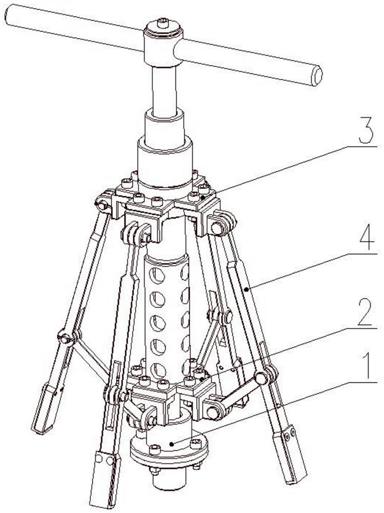
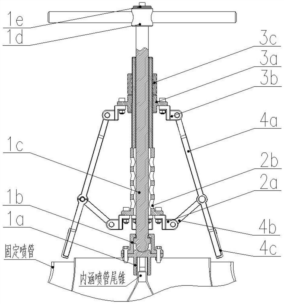
[0031] see figure 1 , is a structural schematic diagram of a puller for removing a fixed nozzle of a small aero-engine provided by an embodiment of the present invention. Such as figure 1 As shown, the small aero-engine fixed nozzle removal puller includes:

[0032] The supporting screw assembly 1 includes a screw 1c and a spherical base 1a fixed on the bottom of the screw 1c, and the spherical base 1a is set on the inner nozzle tail cone of the engine;

[0033] The lower slider assembly 2 includes a threaded sleeve 2b and a plurality of first external brackets 2a, the threaded sleeve is sleeved on the screw 1c, and one end of the external bracket is connected to the threaded sleeve;

[0034] The upper slider assembly 3 includes a sliding sleeve 3a and a plurality of second external brackets 3b, the sliding sleeve 3a is slidably sleeved on the threaded sleeve 2b, and one end of the second external bracket ...


PUM


Abstract

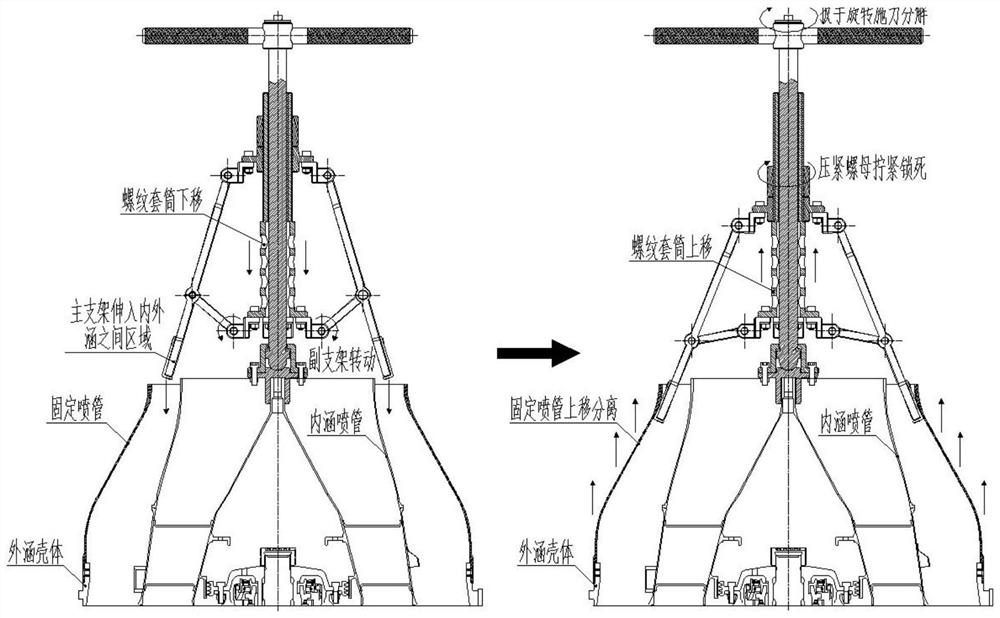
The invention discloses a puller for removing a fixed nozzle of a small aero-engine and a method for using the same. The puller supports a spherical base of a screw assembly and fixes it to the end of the tail cone of the inner nozzle of the engine, and adjusts the screw thread of the lower slider assembly. The sleeve moves downwards, so that the rubber part of the main bracket of the telescopic bracket assembly extends into the area between the internal nozzle and the fixed nozzle, and then adjusts the sliding cylinder of the upper slider assembly to move downwards, so that the rubber part of the front end of the main bracket is in contact with the fixed nozzle. The inner wall of the fixed nozzle is in contact with each other, so that the threaded sleeve moves upward, thereby driving the circumferential telescopic bracket assembly to move upward at the same time, and the fixed nozzle is pulled out from the outer culvert shell along the reverse course. The dismantling puller provided in this embodiment and its use method provide an adjustable dismantling puller by adopting a telescopic mechanism and a locking mechanism, etc., to ensure the smooth removal of the fixed nozzle, and to avoid impact and fatigue fracture of components, etc. damage.

Description

technical field [0001] The invention belongs to the field of aviation manufacturing engineering, and relates to a puller for removing a fixed nozzle of a small aeroengine and a use method thereof. Background technique [0002] At present, the tail nozzle of small aero-engines generally adopts a thin-walled fixed nozzle structure. Therefore, during the operation of the engine, the high-temperature and high-pressure gas in the flow channel can easily cause various deformations of the fixed nozzle and the outer shell that it contacts. The stagnation and adhesion caused the tightness of the fit to increase significantly, but at the same time, because the fixed nozzle is a tapered sleeve structure, there is no axial bearing surface required to meet the disassembly requirements. Therefore, when decomposing the fixed nozzle, it mainly relies on the rubber first. The hammer repeatedly strikes the outer wall of the nozzle outward along the circumferential direction, and then relies o...

Claims


Application Information

Patent Timeline
Patent Type & Authority Patents(China)
IPC IPC(8): B25B27/02
CPCB25B27/02
Inventor 付玄刘自成徐广庆杨文波曹冰朱浩淼
Owner AECC SICHUAN GAS TURBINE RES INST
Features
  • R&D
  • Intellectual Property
  • Life Sciences
  • Materials
  • Tech Scout
  • Unparalleled Data Quality
  • Higher Quality Content
  • 60% Fewer Hallucinations
Learn More