Method and device for measuring free-form surface based on comparative measurement of liquid reference plane

A datum plane, comparative measurement technology, used in measurement devices, mechanical measurement devices, optical devices, etc., can solve the problems of surface roughness, undulation, and inclination of the measurement accuracy of the sample, improve accuracy and reduce Abbe error. Effect

Active Publication Date: 2021-03-19
BEIJING INSTITUTE OF TECHNOLOGYGY
View PDF5 Cites 0 Cited by
  • Summary
  • Abstract
  • Description
  • Claims
  • Application Information

AI Technical Summary

Problems solved by technology

[0007] To sum up, the measurement accuracy of the existing measurement methods is greatly affected by the differences in the characteristics of the sample surface such as roughness, undulation, and inclination angle, which is the main technical bottleneck for improving the measurement accuracy of the free-form surface profile.

Method used


Image

  • Method and device for measuring free-form surface based on comparative measurement of liquid reference plane
  • Method and device for measuring free-form surface based on comparative measurement of liquid reference plane
  • Method and device for measuring free-form surface based on comparative measurement of liquid reference plane

Examples


Embodiment 1

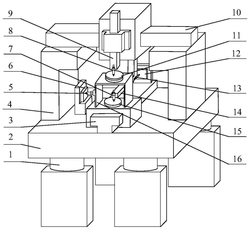
[0037] Such as figure 1 As shown, a free-form surface measurement device based on liquid reference plane comparison measurement, including: active air-floating shock-isolation spring 1, air-floating shock-isolation base 2, X-direction air-floating guide rail 3, gantry frame 4, the first nanometer precision Height measurement sensor 5, first plane flat crystal 6, second nanometer precision height measurement sensor 7, third nanometer precision height measurement sensor 8, Z direction air bearing guide rail 9, Y direction air bearing guide rail 10, free-form surface sample attitude adjustment device 11. The second flat crystal 12, the fourth nanometer precision height measurement sensor 13, the truss 14, the liquid level reference 15, and the support frame 16.

[0038] The connection and positional relationship of the above components are:

[0039] The air flotation isolation base 2 is installed on the active air flotation isolation spring 1; the X-direction air flotation guide...

Embodiment 2

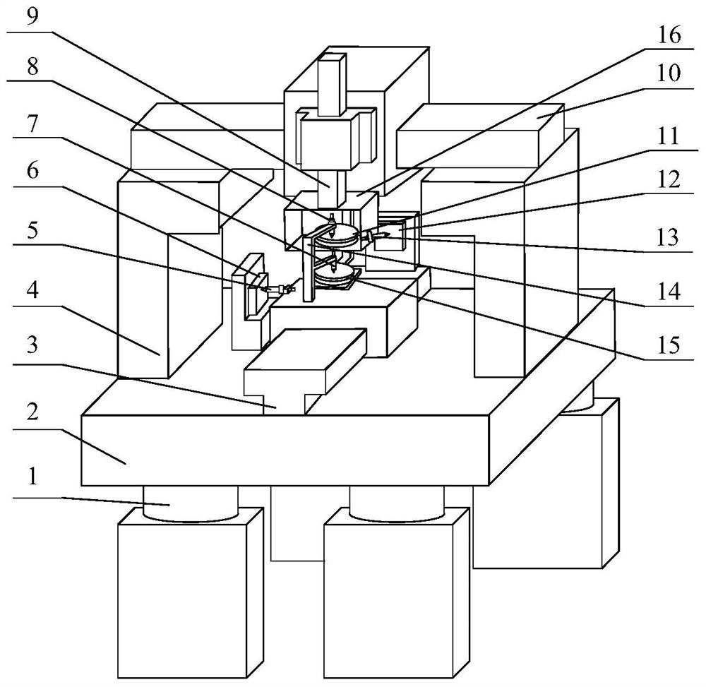
[0047] Such as figure 2 As shown, it includes: active air-floating shock-isolation spring 1, air-floating shock-isolation base 2, X-direction air-floating guide rail 3, gantry frame 4, first nanometer precision height measuring sensor 5, first flat crystal 6, second Nano-precision height measurement sensor 7, third nano-precision height measurement sensor 8, Z-direction air bearing guide rail 9, Y-direction air bearing guide rail 10, free-form surface sample attitude adjustment device 11, second flat crystal 12, fourth nano-precision height Measuring sensor 13, truss 14, liquid level reference 15, support frame 16;

[0048] The connection and positional relationship between the above components are:

[0049] The air flotation isolation base 2 is installed on the active air flotation isolation spring 1; the X-direction air flotation guide rail 3 and the gantry 4 are installed on the air flotation isolation base 2; the Y-direction air flotation guide rail 10 is installed on th...


PUM


Abstract

The invention discloses a free-form surface detection method and device based on liquid reference plane comparison measurement, and belongs to the technical field of optical precision detection. The straightness error of an X-direction air floatation guide rail and a Y-direction air floatation guide rail in the height direction is monitored and compensated by utilizing liquid level reference surface height information acquired by a nano-precision height measurement sensor. Two planar optical flat with the planar precision reaching one twentieth of the wavelength are placed in parallel with theX-direction air floatation guide rail and the Y-direction air floatation guide rail respectively; the two nano-precision height measurement sensors are used for obtaining the distances between the nano-precision height measurement sensors and the two planar optical flat respectively and used for monitoring and compensating transverse straightness errors of the X-direction air floatation guide rail and the Y-direction air floatation guide rail. Dimension reduction error separation is carried out on the surface morphology of the free-form surface by taking a liquid reference plane with high flatness as a reference, and finally nano-precision detection of the surface morphology of the free-form surface is realized. According to the invention, the range and precision of free-form surface measurement are greatly improved.

Description

technical field [0001] The invention relates to a free-form surface detection method and device based on liquid reference plane comparative measurement, which is used for nano-precision detection of free-form surfaces in precision optical systems, and belongs to the technical field of optical precision detection. [0002] technical background [0003] The free-form surface element has the largest degree of freedom in surface morphology, and it is easy to eliminate aberrations in the imaging system. advantages such as sex. Using a free-form surface optical system to replace the previous optical system composed of a plane, a spherical mirror, and a coaxial quadratic mirror to improve imaging quality, reduce system volume and weight, and solve imaging accuracy, portability, and reliability issues has already been achieved. It has become an important trend in the development of optical systems. [0004] However, while free-form surfaces increase the degree of freedom in design,...

Claims


Application Information

Patent Timeline
Patent Type & Authority Patents(China)
IPC IPC(8): G01B11/24G01B5/00
CPCG01B5/0002G01B11/24
Inventor 邱丽荣唐顺赵维谦
Owner BEIJING INSTITUTE OF TECHNOLOGYGY
Why Eureka
Try Eureka