
View axis automatically correcting method for atmospheric laser communication system

An atmospheric laser communication and optical system technology, applied in the transmission system, electromagnetic wave transmission system, electrical components, etc., can solve the problems that cannot be corrected in real time, cannot meet the error correction requirements of the dynamic laser communication system, and achieve high-precision APT control Effect

Inactive Publication Date: 2009-04-01
CHANGCHUN UNIV OF SCI & TECH
View PDF0 Cites 0 Cited by
  • Summary
  • Abstract
  • Description
  • Claims
  • Application Information

AI Technical Summary

Problems solved by technology

This method cannot meet the error correction requirements of the dynamic laser communication system, let alone real-time correction

Method used


Image

  • View axis automatically correcting method for atmospheric laser communication system
  • View axis automatically correcting method for atmospheric laser communication system
  • View axis automatically correcting method for atmospheric laser communication system

Examples


Embodiment 1

[0029] In practical applications, the divergence angle of the laser beam is less than <200μrad, and the communication distance is 6-20km;

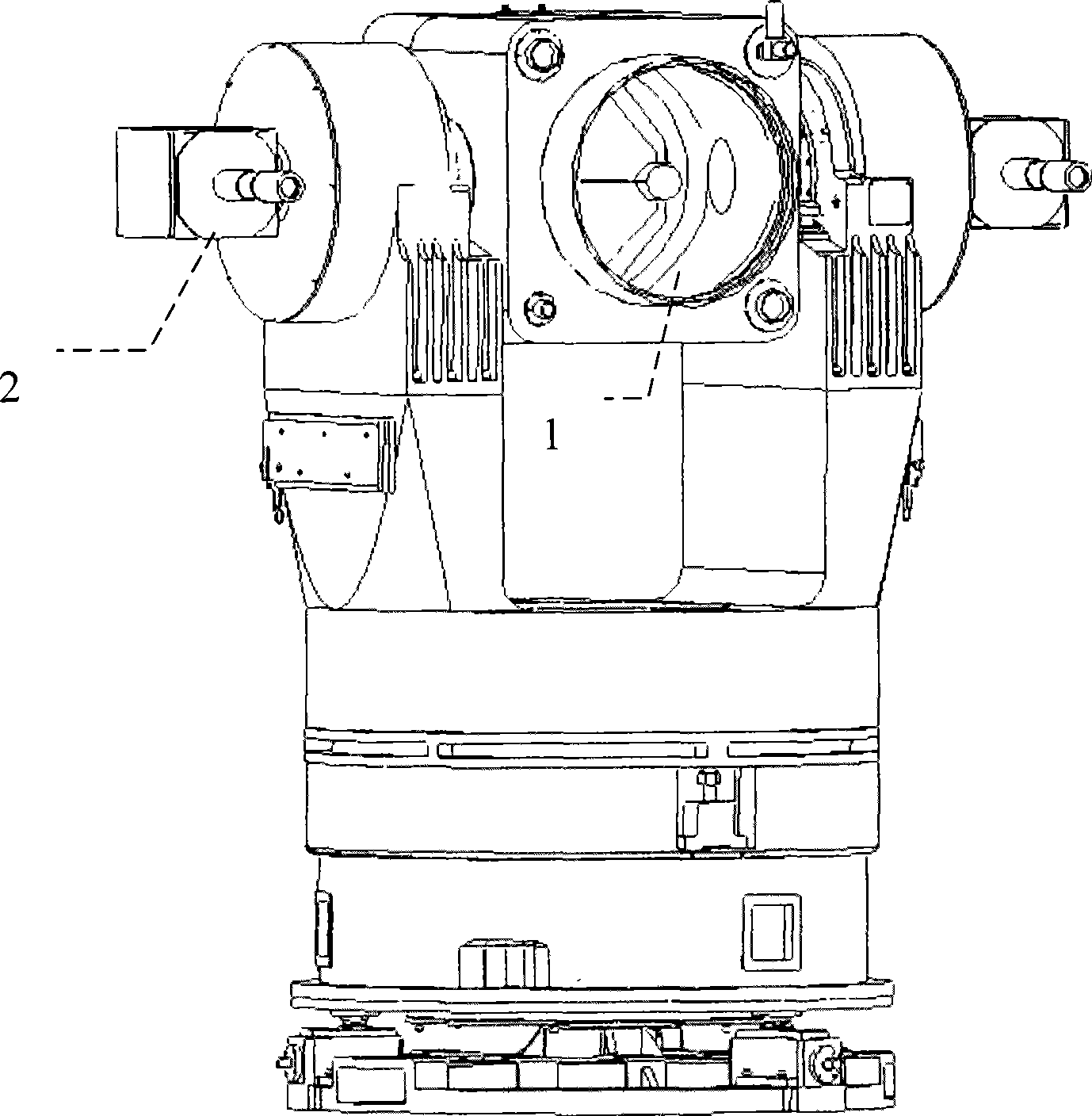
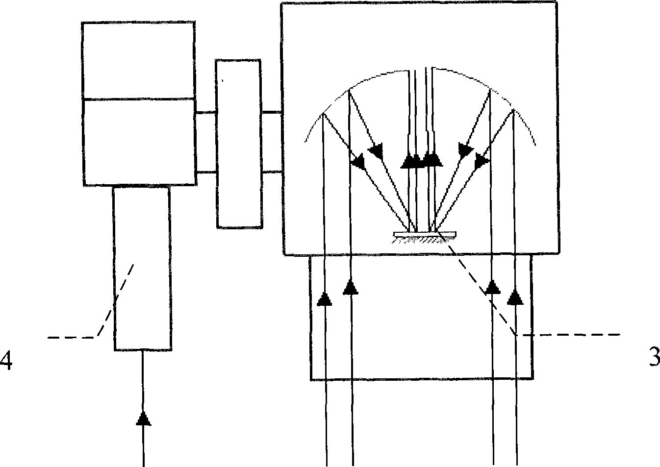
[0030] 1. Required equipment, such as figure 2 Shown: Atmospheric laser communication optical transceiver LG001 primary mirror optical system 3, including Cassegrain system, communication light emitting and receiving subsystems, fine beacon light emitting and receiving subsystems; coarse tracking optical system and CCD imaging and processing system 4; A turntable control computer and GPS equipment are also required;

[0031] 2. Implementation steps:

[0032] (1) The process implemented by this method is as follows: Figure 4 As shown, step 100 is the beginning, that is, to complete the startup of the turntable control computer, the initialization of the program and the peripheral equipment and the system to realize the target capture and enter the tracking state;

[0033] (2) Step 110 is that the turntable control computer receives the...


PUM


Abstract

The invention relates to a method for automatically correcting a visual axis in an atmospheric laser communication system. The method comprises the following conditions and steps: the required equipment comprises a primary mirror optical system, a rough tracking optical system and a CCD imaging and processing system of an atmospheric laser communication optical transmitter and receiver, a turntable control computer and a GPS apparatus. The method is realized by the following steps: after the system is initialized, the target acquisition is realized, the system is in a tracking state, the turntable control computer receives GPS distance information and computes the visual axis deviation angle from different communication distances and CCD pixel elements to be corrected, the pixel elements are transmitted to a DSP processor in the CCD imaging and processing system for processing, thus changing the central position of the imaging and completing correction of a rough finishing axis. When the visual axis is not corrected, the maximum rough tracking error (based on 6km communication distance) can be 186murad, and when the method is adopted, the maximum rough tracking error can completely reach 60murad.

Description

technical field [0001] The invention relates to a method for automatically correcting a visual axis in an atmospheric laser communication system, and belongs to the technical field of laser communication. Background technique [0002] After the appearance of laser in 1960, it provided a highly directional, high coherence, and high brightness light source for optical communication systems, and promoted the development of optical communication technology. Free-space optical communication is less detectable than existing radio-frequency communication because the beam can be directed at a target with a very small divergence angle. Therefore, free-space laser communication is very attractive for communication between two mobile platforms, such as links between satellites, between satellites and the ground, between aircraft, between aircraft and the ground, and between aircraft and satellites. Since the 1970s, the developed countries in the world have started the research work of...

Claims


Application Information

Patent Timeline
Patent Type & Authority Applications(China)
IPC IPC(8): H04B10/00H04B10/11
Inventor 杨阳王小曼刘树昌刘智王彩霞
Owner CHANGCHUN UNIV OF SCI & TECH
Learn More