
Device testing method, device and system

A technology of equipment testing and equipment, which is applied in the computer field, can solve the problems of complex implementation, poor real-time performance, time-consuming and manpower consumption, and achieve the effects of improving accuracy, good real-time performance, saving time and labor costs

Pending Publication Date: 2020-04-03
BEIJING JINGDONG SHANGKE INFORMATION TECH CO LTD +1
View PDF0 Cites 2 Cited by
  • Summary
  • Abstract
  • Description
  • Claims
  • Application Information

AI Technical Summary

Problems solved by technology

[0004] The implementation of the existing scheme is relatively complicated, it takes a lot of time and manpower, the cost is high, and the real-time performance is poor

Method used


Image

  • Device testing method, device and system
  • Device testing method, device and system
  • Device testing method, device and system

Examples


Embodiment Construction

[0034] Exemplary embodiments of the present invention are described below in conjunction with the accompanying drawings, which include various details of the embodiments of the present invention to facilitate understanding, and they should be regarded as exemplary only. Accordingly, those of ordinary skill in the art will recognize that various changes and modifications of the embodiments described herein can be made without departing from the scope and spirit of the invention. Also, descriptions of well-known functions and constructions are omitted in the following description for clarity and conciseness.

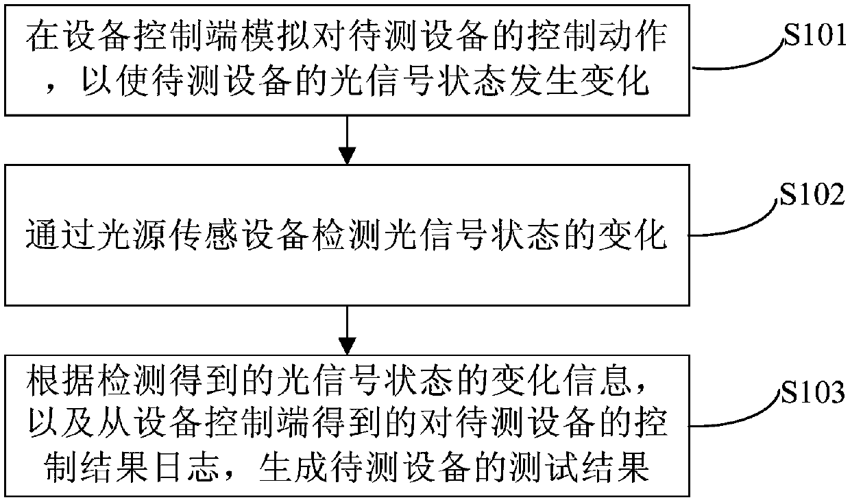
[0035] figure 1 is a schematic diagram of main steps of a device testing method according to an embodiment of the present invention.

[0036] Such as figure 1 As shown, the device testing method in the embodiment of the present invention mainly includes the following steps S101 to S103.

[0037] The equipment testing method of the embodiment of the present invention can...


PUM


Abstract

The invention discloses an device testing method, device and system, and relates to the technical field of computers. One specific embodiment of the method comprises the following steps of simulatingthe control action of a to-be-tested device at an device control end so as to change an optical signal state of the to-be-tested device; detecting the change of the optical signal state through a light source sensing device; and generating a test result of the to-be-tested device according to the change information of the optical signal state obtained by detection and a control result log of the to-be-tested device obtained from the device control end. According to the embodiment, the automatic testing can be carried out through a light source, the device can be tested conveniently without deploying a monitoring system and carrying out image recognition, the time and labor cost are saved, the real-time performance is good, the color value of an optical signal can be detected, and the testing accuracy is improved.

Description

technical field [0001] The present invention relates to the field of computer technology, in particular to an equipment testing method, device and system. Background technique [0002] At present, the IOT (Internet of Things) industry is developing rapidly, but the access of a large number of smart devices has brought a lot of workload to testers, especially testing the stability of a certain device, such as testing a lamp or an indicator light Whether the control of smart devices is stable or not, the existing solutions use video surveillance to implement, and it is necessary to deploy a camera monitoring system, and use image recognition, analysis and other technologies to test the devices. [0003] In the course of realizing the present invention, the inventor finds that there are at least the following problems in the prior art: [0004] Existing solutions are relatively complex to implement, require a lot of time and manpower, have high costs, and have poor real-time p...

Claims


Application Information

Patent Timeline
IPC IPC(8): G01J1/42G01J3/46
CPCG01J1/42G01J3/46
Inventor 侯伟浩万娜
Owner BEIJING JINGDONG SHANGKE INFORMATION TECH CO LTD
Learn More