Measurement method of radio frequency pulse jitters

A technology of radio frequency pulse and measurement method, which is applied in the direction of pulse characteristic measurement, radio frequency circuit test, electronic circuit test, etc., can solve the problems of consuming a lot of manpower and time, affecting the characteristics of pulse jitter, and being unable to achieve high precision of pulse jitter, etc., to improve Accuracy, time and labor cost saving effects

Inactive Publication Date: 2017-09-22
LEIHUA ELECTRONICS TECH RES INST AVIATION IND OF CHINA
View PDF5 Cites 2 Cited by
  • Summary
  • Abstract
  • Description
  • Claims
  • Application Information

AI Technical Summary

Problems solved by technology

[0005] 1. Due to the capacitance characteristics of the detector, it will directly affect the characteristics of pulse jitter, and it is impossible to achieve high-precision (nanosecond level) analysis of pulse jitter
[0006] 2. Due to the limitations of the time a

Method used


Image

  • Measurement method of radio frequency pulse jitters

Examples


Example Embodiment

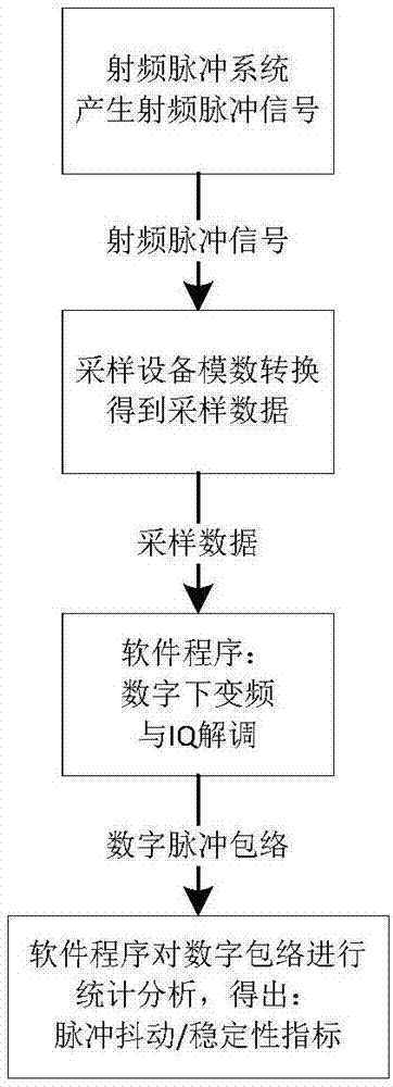
[0039] Example 1: The radio frequency of a radio frequency pulse system is 300MHz, the designed pulse width is 2us, the designed pulse repetition period is 100us, and the pulse jitter is required to be no more than 5 nanoseconds. An oscilloscope with a sampling rate of 1GHz is selected as the sampling device.

[0040] Step 1 (sampling): Connect the RF signal circuit to the oscilloscope probe, set the sampling rate of the oscilloscope to 1GHz, sample the RF pulse signal, obtain the sampling data within the time range of 100ms, and store it as a data file.

[0041] Step 2 (digital down-conversion): use software programs (such as Mat lab or Visual Studio tools) to perform digital down-conversion and IQ demodulation on the sampling data and 300MHz digital signal, and calculate the modulus to obtain the digital signal of the pulse envelope . (Because the sampling frequency is 1GHz, the accuracy of the pulse envelope digital signal is 1 nanosecond. Since the pulse repetition period...

Example Embodiment

[0043] Example 2: The radio frequency of a narrowband radio frequency pulse system is 2.33 GHz, the designed pulse width is 2 us, the designed pulse repetition period is 100 us, and the pulse jitter is required to be no more than 5 nanoseconds. A sampling device with a channel bandwidth of 5 GHz and a sampling rate of 1 GHz is selected.

[0044] Step 1 (sampling): Connect the RF signal circuit to the probe of the sampling device, set the sampling rate of the sampling device to 1GHz, sample the RF pulse signal, obtain the sampling data within the time range of 100ms, and store it as a data file.

[0045] Step 2 (digital down-conversion): use software programs (such as tools such as Mat lab or Visual Studio) to perform digital down-conversion and IQ demodulation on the sampled data and 0.33GHz digital signal, and calculate the modulus to obtain the digital pulse envelope Signal.

[0046] Step 3: Repeat Step 3 of Example 1.

[0047] A method for measuring radio frequency pulse ...


PUM


Abstract

The invention discloses a measurement method of radio frequency pulse jitters and belongs to the radio frequency signal test technical field. The method comprises the following steps that: (1) radio frequency pulse signals are sampled, and sampled data are obtained and stored as a data file; (2) a software program is utilized to perform digital down-conversion and IQ demodulation on the sampled data and local oscillation signals, a modulus is solved, and digital signals of pulse envelops are obtained, and the local oscillation signals are digital signals of a corresponding radio frequency; (3) software is utilized to perform statistics, so that pulse jitter indicators are obtained, wherein the pulse jitter indicators are composed of the pulse width mean value, pulse width jitter mean value, pulse width jitter variance, maximum pulse width difference value, pulse repetition period jitter mean value and jitter variance of all pulse samples; and (4) whether the pulse jitter indicators obtained in the step (3) satisfy requirements is judged. With the measurement method of the invention adopted, the high-precision analysis of the radio frequency pulse jitters can be realized, and the statistics and quantitative analysis of a large number of pulse jitters can be also realized.

Description

technical field [0001] The invention belongs to the technical field of radio frequency signal testing, and in particular relates to a method for measuring radio frequency pulse jitter. Background technique [0002] In the development of the RF pulse system, it is necessary to measure the index of the RF pulse jitter to judge the stability of the pulse signal. Pulse jitter usually consists of two metrics: pulse width jitter and pulse repetition period jitter. Pulse width jitter refers to the difference between pulse widths among several different pulses; pulse repetition period jitter refers to the difference between several different pulse repetition periods. The smaller the two differences, the higher the stability of the pulse signal. [0003] At present, a detector is generally used to detect the pulse envelope of the radio frequency signal, and an oscilloscope is used to observe the pulse envelope, read multiple pulse width values, pulse repetition period values, etc.,...

Claims


Application Information

Patent Timeline
IPC IPC(8): G01R29/02G01R31/28
CPCG01R29/02G01R31/2822
Inventor 刘睿
Owner LEIHUA ELECTRONICS TECH RES INST AVIATION IND OF CHINA
Why Eureka
Try Eureka