Flat wire twisting device for armature winding end part of flat wire motor

A technology of armature winding and flat wire is applied in the field of flat wire twisting device at the end of armature winding of flat wire motor. , The effect of saving manpower and time

Pending Publication Date: 2020-04-03
ZHEJIANG LOONGSON ELECTRIC DRIVE TECH CO LTD
View PDF1 Cites 6 Cited by
  • Summary
  • Abstract
  • Description
  • Claims
  • Application Information

AI Technical Summary

Problems solved by technology

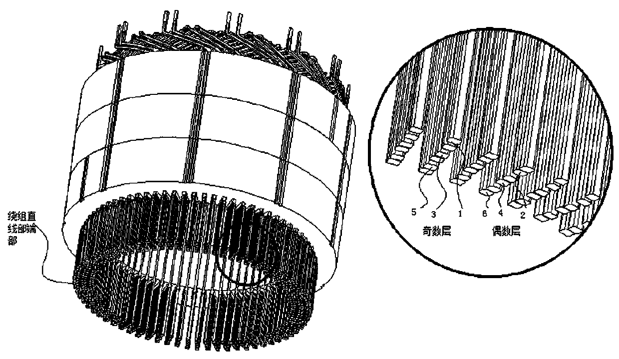
In order to meet the twisting requirements required by this method, the twisting device needs to be highly coordinated with the person to perform twisting in every two layers from the outermost straight line part to the innermost straight line part. The steps of this method are cumbersome and require every two It takes a lot of time and effort to replace the different twisting molds once and twist them three times to achieve the effect.

Method used


Image

  • Flat wire twisting device for armature winding end part of flat wire motor
  • Flat wire twisting device for armature winding end part of flat wire motor
  • Flat wire twisting device for armature winding end part of flat wire motor

Examples


Embodiment 1

[0031] Such as Figure 4-7 As shown, a twisting device for forming the end of the armature winding of a flat wire motor is used for twisting the flat enameled wire at the end of the armature winding of a flat wire motor during the forming process of the end of the armature winding of a flat wire motor. It includes an ejection mechanism, a twisting mechanism, a power mechanism, and an upper support plate 4 and a lower support plate 5 that are oppositely arranged.

[0032] The ejection mechanism includes an ejection rod 11 , a cylinder 12 and an ejection disc 13 . One end of the ejector rod 11 is connected to the cylinder 12, and the ejector disc 13 is coaxially arranged at the other end of the ejector rod. Cylinder 12 is fixed on lower support plate 5, and ejector rod 11 stretches out upper support plate 4.

[0033] The twisting mechanism is installed between the upper and lower support plates. It includes a plurality of first gears 21 arranged up and down along the same cir...


PUM


Abstract

The invention belongs to the technical field of motor armature winding manufacturing, and particularly relates to a flat wire twisting device for an armature winding end part of a flat wire motor. Theflat wire twisting device comprises: an ejection mechanism comprising an ejection rod and an ejection disc which is coaxially arranged on the ejection rod; a twisting mechanism comprising a pluralityof wire inserting holes formed in the circumferential direction of the ejection rod; and a power mechanism used for driving the twisting mechanism to enable the wire inserting holes to rotate in thecircumferential direction of the ejection rod. A stator core is fixed on the ejection disc, the linear parts of the U-shaped wires in the armature winding are inserted into the wire inserting holes, and when the power mechanism drives the twisting mechanism to rotate, the wire inserting holes drive the parts, located in the wire inserting holes, of the linear parts of the U-shaped wires to rotaterelative to the stator core so as to bend the linear parts. Work steps can be saved, manpower and time are saved, and production efficiency is improved.

Description

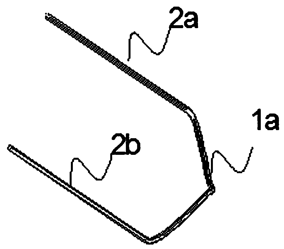
technical field [0001] The invention belongs to the technical field of motor armature winding production, in particular to a flat wire twisting device at the end of a flat wire motor armature winding. Background technique [0002] The armature is an important part of the motor. The armature is composed of two main parts: the stator core and the winding. The armature winding refers to the enamelled copper wire installed on the armature by winding or plugging. [0003] With the development of the times, in order to pursue high efficiency and small size in drive motors used in electric vehicles or other fields, enamelled flat wires with a rectangular cross-section have been used as motor windings. This kind of flat copper wire is formed into a U-shaped wire that is roughly U-shaped and roughly has a meandering portion 1a, a first straight portion 2a, and a second straight portion 2b (such as Figure 1 shown) and inserted into the slot of the stator core, assembled with the stat...

Claims


Application Information

Patent Timeline
IPC IPC(8): H02K15/00
CPCH02K15/0068
Inventor 王丽
Owner ZHEJIANG LOONGSON ELECTRIC DRIVE TECH CO LTD
Why Eureka
Try Eureka