A Circuit for Accurately Correcting the Duty Cycle of Clock Signal

A technology of clock signal and duty cycle, which is applied in the direction of transforming continuous pulse chains into pulse chain devices with required modes, and can solve problems such as limited, large chip area, and high current

Active Publication Date: 2020-08-11
ASR SMART TECH CO LTD
View PDF8 Cites 2 Cited by
  • Summary
  • Abstract
  • Description
  • Claims
  • Application Information

AI Technical Summary

Problems solved by technology

[0006] Existing means for generating precise duty-cycle clock signals are limited and typically require a relatively large chip area and consume a large amount of current

Method used


Image

  • A Circuit for Accurately Correcting the Duty Cycle of Clock Signal
  • A Circuit for Accurately Correcting the Duty Cycle of Clock Signal
  • A Circuit for Accurately Correcting the Duty Cycle of Clock Signal

Examples


Embodiment Construction

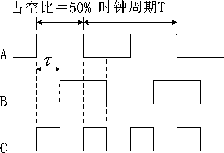
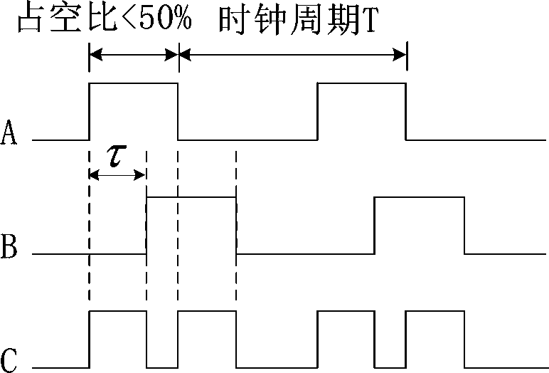
[0059] see Figure 9 , which is Embodiment 1 of the clock signal duty ratio correction circuit provided in this application. The clock signal duty ratio correction circuit 100 includes an inverter chain 110 , a delay unit 120 , a phase detection unit 130 and a low-pass filter 140 . The input signal CLKIN is input to the input end of the inverter chain 110, and the duty ratio of the input signal CLKIN is adjusted by changing the gate bias voltage of the first CMOS inverter in the inverter chain 110, and the inverter chain 110 outputs the output signal CLKOUT after the duty ratio correction to the outside. The output signal CLKOUT passes through the delay unit 120 to obtain a delayed signal, and the output terminal of the delay unit 120 is called a node VC. The output signal CLKOUT and the delay signal are used as the input of the phase detection unit 130. The phase detection unit 130 outputs an indication signal representing whether the duty ratio of the output signal CLKOUT ...


PUM


Abstract

The invention discloses a circuit for accurately correcting the duty ratio of a clock signal. The circuit comprises an inverter chain, a delay unit, a phase detection unit and a low-pass filter. The inverter chain adopts one CMOS inverter or adopts a plurality of cascaded CMOS inverters. An input signal enters the input end of the inverter chain. The duty ratio of the input signal is adjusted through the change of the grid bias voltage of the first CMOS inverter in the inverter chain, and the inverter chain outputs an output signal subjected to duty ratio correction. And the output signal passes through the time delay unit to obtain a time delay signal. The output signal and the delay signal are used as input of the phase detection unit together, and the phase detection unit outputs an indication signal representing whether the duty ratio of the output signal reaches a target value or not. After high-frequency components of the indication signals are filtered out through a low-pass filter, the remaining low-frequency and direct-current components serve as grid direct-current bias voltage of a first CMOS inverter in the inverter chain. The duty ratio of the output signal can be accurately controlled.

Description

technical field [0001] The present application relates to a circuit for correcting the duty cycle, in particular to a circuit for correcting the duty cycle of a clock signal. Background technique [0002] In modern circuit systems, the clock signal is the most commonly used signal, which can be generated by a crystal oscillator or a ring oscillator. Different circuit modules have different requirements on the clock signal. For example, the analog-to-digital converter requires the edge jitter of the input clock signal to be particularly small; the real-time clock circuit (RTC) requires the frequency of the input clock signal to be very stable; the mixer (Mixer) in some radio frequency circuits requires a local oscillator (LO ) The clock signal generated has a duty cycle other than 50% to achieve the purpose of increasing the conversion gain, the most commonly used is a clock signal with a 25% duty cycle; however, the double frequency circuit (Doubler) requires a duty cycle o...

Claims


Application Information

Patent Timeline
Patent Type & Authority Patents(China)
IPC IPC(8): H03K5/156
CPCH03K5/156
Inventor 刘俊路超
Owner ASR SMART TECH CO LTD
Why Eureka
Try Eureka