Full-body massage chair and chair frame structure thereof

A massage chair and chair frame technology, which is applied in the direction of roller massage, massage auxiliary products, passive exercise equipment, etc., can solve the problem of high cost and achieve the effect of improving massage comfort

Active Publication Date: 2020-04-07
NINGBO BINGHANG ELECTRONICS SCI & TECH CO LTD
View PDF10 Cites 14 Cited by
  • Summary
  • Abstract
  • Description
  • Claims
  • Application Information

AI Technical Summary

Problems solved by technology

[0006] In order to solve the aforementioned technical problems, another applicant applied for a Chinese patent titled a multi-movement full-range massage chair with the announcement number CN203303313U. This patent adopts the technical solution of setting two massage movements. Obviously, the cost higher

Method used


Image

  • Full-body massage chair and chair frame structure thereof
  • Full-body massage chair and chair frame structure thereof
  • Full-body massage chair and chair frame structure thereof

Examples


Embodiment 1

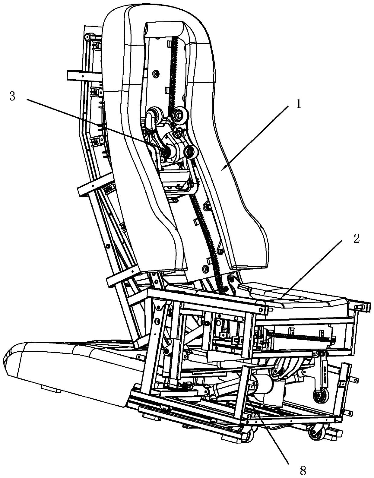
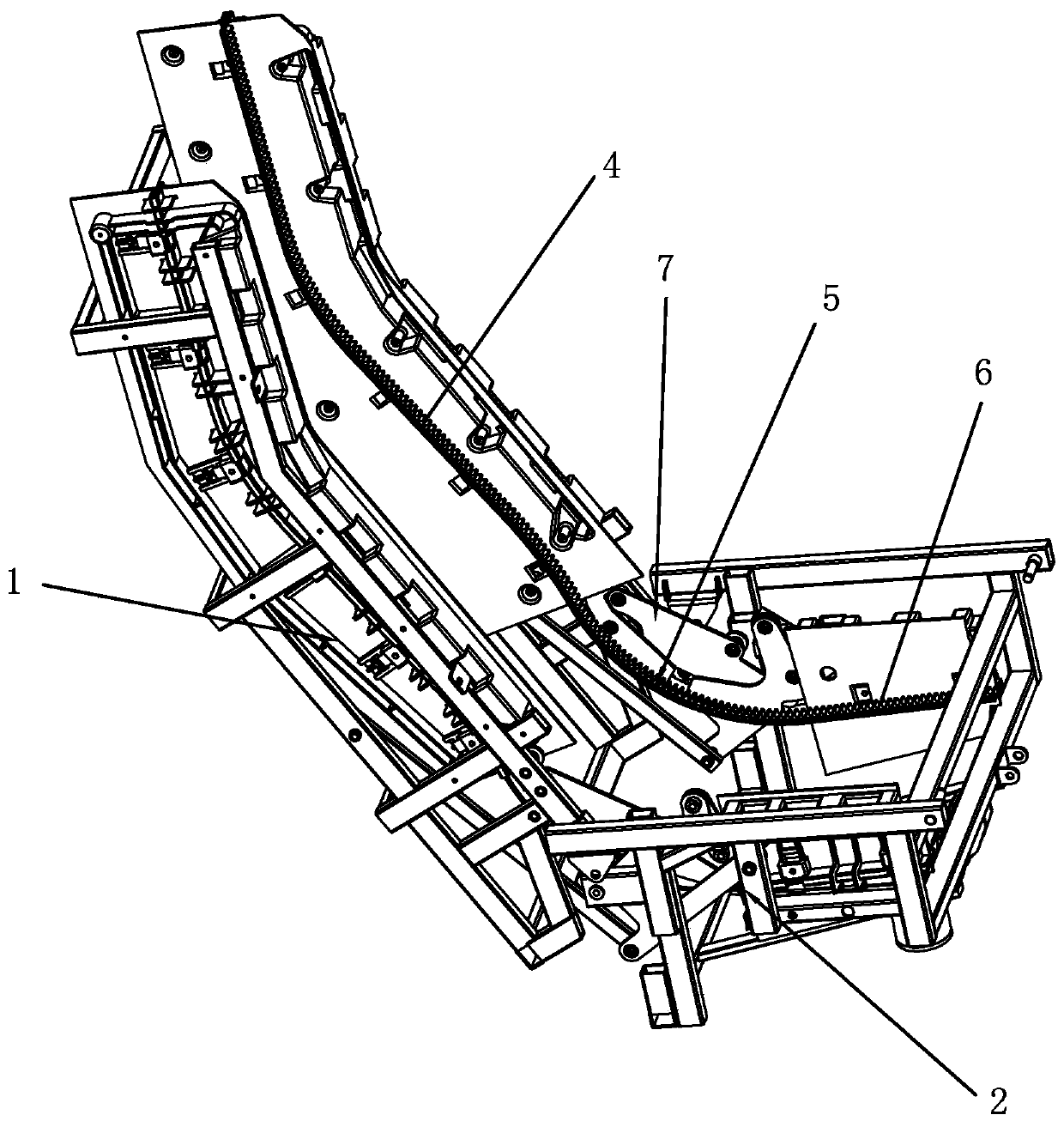
[0046] see Figure 1 to Figure 12 As shown, a whole body massage chair provided in this embodiment can perform massage actions from the back to the legs of the healer, and it includes a chair frame structure and a massage movement 3 arranged on the chair frame to reciprocate. The frame includes a back frame 1, a seat frame 2 and a base 8, wherein the back frame 1 is used for the practitioner to lean on, and it is fixedly installed with a back guide rail for the massage movement 3 to reciprocate along the length direction of the practitioner's back 4; wherein the seat frame 2 is used for the practitioner to take a seat, and it is fixedly installed with a seat guide rail 6 for the massage movement 3 to reciprocate along the length direction of the practitioner's legs; Rotate around the set axis to adjust the treatment angle between it and the seat frame 2. There is a gap between the back guide rail 4 and the seat guide rail 6; The link mechanism 5 of the guide rail 6 is used fo...

Embodiment 2

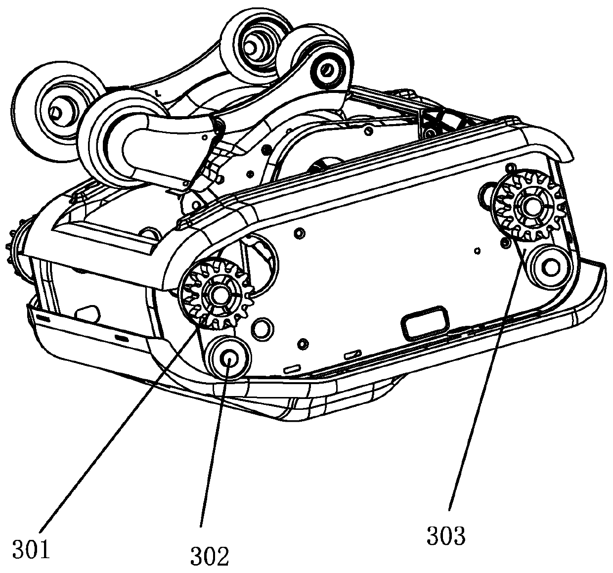
[0068] Such as Figure 13 shown, and refer to image 3 As shown, the basic structure of this embodiment is basically the same as that of Embodiment 1, except that the transition rail 501 in this embodiment is located below the elastic plate 502 . In order to adapt to this structure, the running wheel 301 of the massage movement 3 in this embodiment is located below the transition rail 501 , and the clamping wheel 302 is located above the elastic plate 502 .

[0069] The working principle of the present invention is as follows:

[0070] When the present invention is working, the control device first drives the chair frame and the massage core 3 back to the initial position, and then controls the massage core 3 to detect the body curve. When detecting the body curve, the massage movement 3 now moves to the highest point on the back guide rail 4, and then moves downwards to detect the shoulders, back and waist successively. After the back curve detection is completed, in the m...


PUM


Abstract

The invention relates to the field of massage appliances, and specifically discloses a whole-body massage chair and a chair frame structure thereof. The chair frame comprises a back frame, which is fixedly provided with a back guide rail; a seat frame is fixedly equipped with a seat guide rail; the back frame adjusts the treatment angle between the back frame and the seat frame by rotating about aset axis, and the place where the back guide rail and the seat guide rail are adjoined has a spacing gap; a linkage mechanism for connecting the back guide rail and the seat guide rail is arranged atthe spacing gap so as to enable a massage movement to smoothly walk from the back frame to the seat frame to massage legs, and the linkage mechanism comprises a transition guide rail and an elastic plate, wherein the elastic plate is driven by the rotational motion of the back frame and/or the seat frame to generate elastic deformation, the transition guide rail and the elastic plate are fixedlyconnected, and both the elastic plate and the transition guide rail are arc-shaped; and the back frame and/or the seat frame are/is provided with a deformation holding mechanism followed by the back frame and/or the seat frame, and the deformation holding mechanism is pressed against the elastic plate and/or the transition guide rail. According to the invention, full-body massage can be realized,and the massage comfort is improved.

Description

technical field [0001] The invention relates to the field of massage appliances, in particular to a whole-body massage chair and its frame structure. Background technique [0002] The interior of the massage chair is equipped with a massage movement, and a track is set inside the chair. The massage movement moves up and down in the massage chair along the track, playing the role of massage. Now most of the massage chairs can freely adjust the angle to improve comfort. The user's demand for massage is constantly increasing, hoping to imitate manual massage, and to be able to massage the whole body. Due to the structural orientation of most massage movements, the guide rails are only set in the back frame, and the seat frame is due to the angle between the back frame and the seat frame. It needs to be adjusted. The structure of the massage mechanism is complicated, and it cannot be directly walked into the seat frame from the back frame. The moving structure is usually a struc...

Claims


Application Information

Patent Timeline
Patent Type & Authority Applications(China)
IPC IPC(8): A61H1/00
CPCA61H1/00A61H2201/0149A61H2205/081A61H2205/10A61H2203/0425A61H15/0078A61H2015/0057A61H2201/1669A61H2201/0165A61H2201/1676A61H2201/0192A61H2201/149A61H37/00
Inventor 袁挺何彦忠陆鹏张玉玲
Owner NINGBO BINGHANG ELECTRONICS SCI & TECH CO LTD
Why Eureka
Try Eureka