Sheet metal part feeding and conveying mechanism

A technology of conveying mechanism and sheet metal parts, applied in the field of sheet metal parts processing, can solve the problems of less primary material reserves, inconvenient maintenance in the later period, complicated equipment structure, etc. Effect

Active Publication Date: 2020-04-07
安徽好派文化体育用品股份有限公司
View PDF7 Cites 11 Cited by
  • Summary
  • Abstract
  • Description
  • Claims
  • Application Information

AI Technical Summary

Problems solved by technology

It avoids manually moving the sheet metal parts to the stamping machine one by one for stamping, which improves the production efficiency. However, this eq

Method used


Image

  • Sheet metal part feeding and conveying mechanism
  • Sheet metal part feeding and conveying mechanism
  • Sheet metal part feeding and conveying mechanism

Examples


Embodiment Construction

[0025] The following will clearly and completely describe the technical solutions in the embodiments of the present invention with reference to the accompanying drawings in the embodiments of the present invention. Obviously, the described embodiments are only some, not all, embodiments of the present invention. Based on the embodiments of the present invention, all other embodiments obtained by persons of ordinary skill in the art without making creative efforts belong to the protection scope of the present invention.

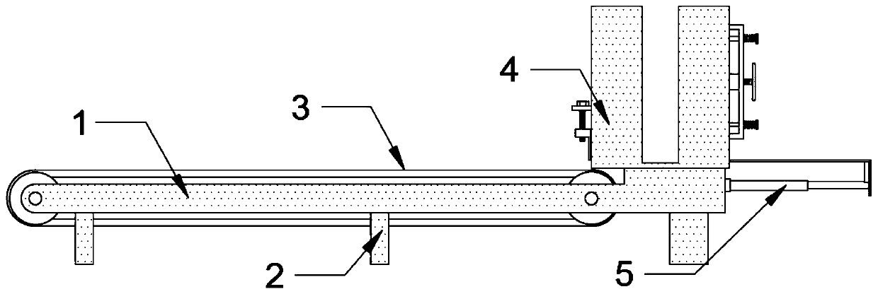
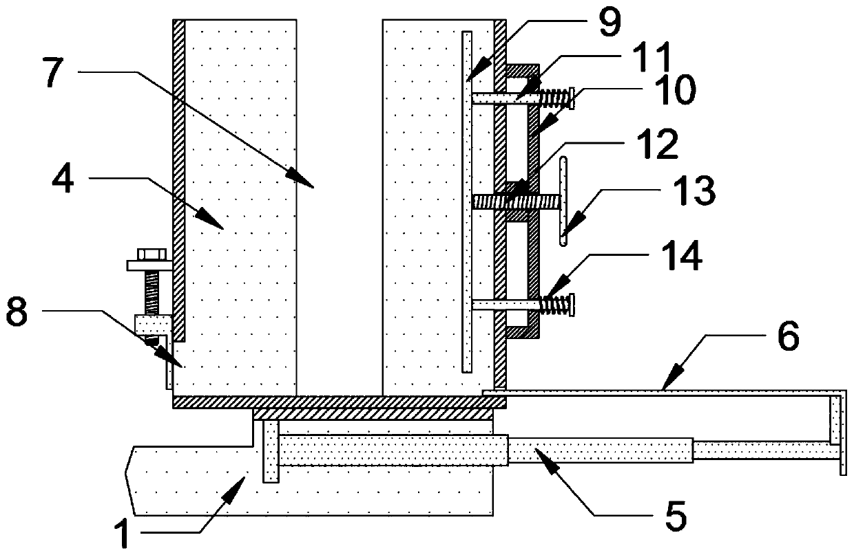
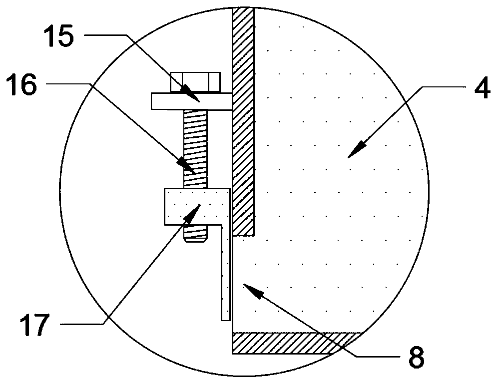
[0026] see Figure 1-3 , the present invention provides a technical solution: a feeding and conveying mechanism for sheet metal parts, including a side plate 1, a foot plate 2, a conveyor belt 3, a material box 4, an electric push rod 5, a push plate 6, a discharge port 8, a limit Plate 9, auxiliary frame 10, guide rod 11, wire post 12 and return spring 14, the side plates 1 are symmetrically placed, and the bottom of the side plates 1 is fixed with a foot pla...


PUM


Abstract

The invention discloses a sheet metal part feeding and conveying mechanism. The mechanism comprises side plates, a foot plate, a conveying belt, a material box, an electric push rod, a push plate, a discharge port, a limiting plate, an auxiliary frame, guide rods, studs and reset springs. The side plates are symmetrically arranged; foot plates are fixed to the bottoms of the side plates. The conveying belt is mounted between the side plates; the material box is fixed to the tops of the side plates and located at the end of the conveying belt. The discharge port is formed in the bottom end of the side, close to the conveying belt, of the material box; the push plate is inserted into the bottom end of the symmetric side of the discharge port of the material box in a sliding manner; the pushplate is attached to the bottom surface of the material box; the electric push rod is installed in the bottom surface of the material box, and the output end of the electric push rod is fixedly connected with the push plate,. According to the sheet metal part feeding and conveying mechanism, through mechanical intermittent operation, sheet metal parts are guided out and fed evenly, work is stable,feeding is efficient, manpower is saved, the production cost is reduced, the feeding period of the device is longer, the structure of the device is simple, and maintenance is convenient and fast.

Description

technical field [0001] The invention relates to the technical field of sheet metal processing, in particular to a sheet metal feeding and conveying mechanism. Background technique [0002] The existing patent CN207592654U provides a sheet metal stamping and feeding device for power distribution cabinets, including a material rack frame. A material rack bottom plate is moved on the material rack frame. Several lifting areas are distributed on the material rack bottom plate. Material retaining rods are respectively arranged around the lifting area, and lifting plates are respectively arranged in each lifting area, and sheet metal parts to be stamped are stacked on the lifting plates; lifting stations are formed on the material rack frame, and the lifting stations A lifting device for driving the lifting plate to perform lifting motion is provided. It avoids manually moving the sheet metal parts to the stamping machine one by one for stamping, which improves production efficie...

Claims


Application Information

Patent Timeline
IPC IPC(8): B65G65/44B65G47/04B65G47/44B65G65/23
CPCB65G47/04B65G47/44B65G65/23B65G65/44
Inventor 潘伟
Owner 安徽好派文化体育用品股份有限公司
Why Eureka
Try Eureka