
Thread take-up mechanism of industrial sewing machine

A technology for industrial sewing machines and thread take-up devices, which is applied in the direction of sewing machine thread take-up devices, sewing machine components, sewing equipment, etc., and can solve problems such as not having the function of weaving thread finishing, difficult-to-weave threads, easy entanglement and knotting, etc. Achieve the effect of stable and reliable transmission structure, smooth body and sufficient deflection power

Active Publication Date: 2020-04-07
DONGGUAN UNIV OF TECH
View PDF5 Cites 0 Cited by
  • Summary
  • Abstract
  • Description
  • Claims
  • Application Information

AI Technical Summary

Problems solved by technology

[0003] The existing thread take-up mechanism does not have the function of arranging the weaving thread in the process of leading the thread. The weaving thread is easy to be entangled and knotted, and it is difficult to clean the weaving thread, so that there are many flocs around the weaving thread, especially For some special weaving threads, if the weaving thread is introduced into the thread take-up mechanism without being tightened, it is easy to cause the floc around the thread to be separated from the thread body due to actions such as thread picking, threading, and piercing, resulting in The problem of thread breakage

Method used


Image

  • Thread take-up mechanism of industrial sewing machine
  • Thread take-up mechanism of industrial sewing machine
  • Thread take-up mechanism of industrial sewing machine

Examples


Embodiment Construction

[0034] The following will clearly and completely describe the technical solutions in the embodiments of the present invention with reference to the accompanying drawings in the embodiments of the present invention. Obviously, the described embodiments are only some, not all, embodiments of the present invention.

[0035] In the description of the present invention, unless otherwise stated, the meaning of "plurality" is two or more; the terms "upper", "lower", "left", "right", "inner", "outer" , "front end", "rear end", "head", "tail", etc. indicate the orientation or positional relationship based on the orientation or positional relationship shown in the drawings, and are only for the convenience of describing the present invention and simplifying the description, rather than Indicates or implies that the device or element referred to must have a particular orientation, be constructed and operate in a particular orientation, and therefore should not be construed as limiting the...


PUM


Abstract

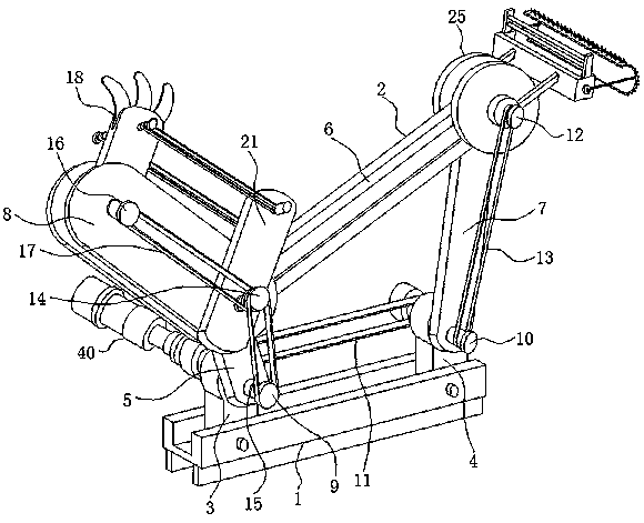
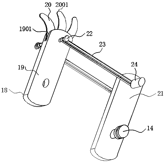
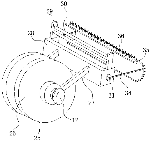
The invention discloses a thread take-up mechanism of an industrial sewing machine, and relates to the technical field of thread take-up mechanisms of sewing machines. Specifically, the thread take-upmechanism comprises a base, a four-bar linkage mechanism, a thread take-up device, a thread arranging device and an adjusting device, wherein the four-bar linkage mechanism is mounted above the base;a fourth connecting arm is connected to one side of the upper part of the four-bar linkage mechanism; the thread take-up device is mounted on the fourth connecting arm; the thread arranging device ismounted on the other side of the upper part of the four-bar linkage mechanism; the bottom driving end of the four-bar linkage mechanism is connected with the adjusting device; the thread arranging device comprises a mounting frame, connecting rods, a thread arranging frame and a thread arranging plate; the connecting rods are mounted in the centers of the outer walls of the two sides of the mounting frame; vertical plates are vertically welded to the two sides of the upper part of the thread arranging frame; and a thread twisting mechanism is composed of a seat cylinder, a movable column anda curved sponge bar. According to the thread take-up mechanism of the industrial sewing machine, the thread arranging device is arranged, so that the problems that weaving threads are easily wound andknotted and fluffs around thread bodies of the weaving threads are relatively numerous are solved.

Description

technical field [0001] The invention relates to the technical field of a thread take-up mechanism of a sewing machine, in particular to a thread take-up mechanism of an industrial sewing machine. Background technique [0002] When the sewing machine is sewing, in the process of forming the stitches, the mechanism that plays the role of conveying, recovering the needle thread and tightening the stitches is called the thread take-up mechanism. The thread take-up mechanism can be divided into five categories according to the structure and principle, that is, the cam pick Thread take-up mechanism, connecting rod thread take-up mechanism, slide bar thread take-up mechanism, rotary thread take-up mechanism and needle bar thread take-up mechanism. It is the connecting rod of the four-bar linkage mechanism. [0003] The existing thread take-up mechanism does not have the function of arranging the weaving thread in the process of leading the thread. The weaving thread is easy to be ...

Claims


Application Information

Patent Timeline
IPC IPC(8): D05B49/00
CPCD05B49/00
Inventor 赵土钦柯志江罗志雄何崇希谢宇尹玲武静
Owner DONGGUAN UNIV OF TECH
Learn More