Water heater

A technology for water heaters and water channels, applied in water heaters, fluid heaters, lighting and heating equipment, etc., can solve the problems of difficult operation, poor control of the amount of addition, complicated addition methods, etc., to achieve improved water flow, long service life, release slow effect

Active Publication Date: 2020-04-07
QINGDAO ECONOMIC & TECHN DEV ZONE HAIER WATER HEATER
7 Cites 1 Cited by

AI-Extracted Technical Summary

Problems solved by technology

This solution needs to add liquid antiscalant, the amount of addition is not e...

Method used

Described antiscaling device both can be installed in the water outlet end of water inlet pipe 2, also can be installed on the pipe body of water inlet pipe 2, when being installed on water inlet pipe 2 pipe bodies, between inlet pipe 2 and antiscaling device Connected, that is, all or part of the water in the water inlet pipe 2 flows into the antiscaling device. The antiscalant contained in the accommodation chamber 4 is a granular solid filter material. After soaking in water, a scale inhibition factor is generated, and the saturation concentration of the antiscalant in water is lower than 3mg/L. Set the antiscaling device in the inner tank 1 without occupying the external space; use the antiscaling principle of the scale inhibition factor generated after the dissolution of the solid granular antiscalant to avoid blocking the water inlet pipe 2; at the same time, the solubility of the antiscalant is low, saturated Low concentration, long service life, eliminating the trouble of frequent replacement or addition of antiscalant. The anti-scaling device is arranged on the water inlet pipe 2, and all/part of the water flowing out of the water inlet pipe 2 passes through the anti-scaling device and then heated to produce little or no scale.
[0047] By setting the baffle plate 5 in the water channel 6, the direction of water flow can be improved, so that the internal temperature distribution of the liner 1 is more regular, so as to improve the output rate of hot water. The accommodating chamber 4 is arranged at any position of the baffle plate 5, and the number of the accommodating chamber 4 is at least one, preferably, the number of the accommodating chamber 4 is two, as shown in Fig. 2 and Fig. 6 As shown, and the two accommodating chambers 4 are located at both ends of the baffle plate 5, at this time, water outlets can be provided at both ends of the water channel 6, and the water flowing out from the water inlet pip...

Abstract

The invention belongs to the field of water heaters, and particularly discloses a water heater. The water heater comprises an inner container and a water inlet pipe. The water inlet pipe is arranged in the inner container, and a scale inhibiting device is further included and is located in the inner container and arranged on the water inlet pipe. The scale removing device comprises a storage chamber containing a scale inhibitor, and after the scale inhibitor in the storage chamber is dissolved, the scale inhibitor is mixed with water flowing out of the water inlet pipe to enter the inner container. According to the water heater, the scale inhibiting device is arranged in the inner container, no external space is occupied, the water inlet pipe is not influenced, and the situation that the water inlet pipe is blocked is avoided; and meanwhile the scale inhibiting device is high in scale inhibiting efficiency, good in scale inhibiting effect and long in service life.

Application Domain

Technology Topic

Image

  • Water heater
  • Water heater
  • Water heater

Examples

  • Experimental program(1)

Example Embodiment

[0041] In order to make the objectives, technical solutions and advantages of the embodiments of the present invention clearer, the technical solutions in the embodiments will be described clearly and completely in conjunction with the accompanying drawings in the embodiments of the present invention. The following embodiments are used to illustrate the present invention. , But not used to limit the scope of the present invention.
[0042] In the description of the present invention, it should be noted that the orientation or positional relationship indicated by the terms "inner", "outer", etc. are based on the orientation or positional relationship shown in the drawings, and is only for the convenience of describing the present invention and simplifying the description. It does not indicate or imply that the pointed device or element must have a specific orientation, be configured and operated in a specific orientation, and therefore cannot be understood as a limitation of the present invention.
[0043] In the description of the present invention, it should be noted that the terms "installed", "connected", "connected", "contacted" and "connected" should be understood in a broad sense, unless clearly defined and defined otherwise. For example, they may be The fixed connection can also be a detachable connection or an integral connection; it can be a mechanical connection or an electrical connection; it can be a direct connection or an indirect connection through an intermediate medium. For those of ordinary skill in the art, the specific meanings of the above-mentioned terms in the present invention can be understood in specific situations.
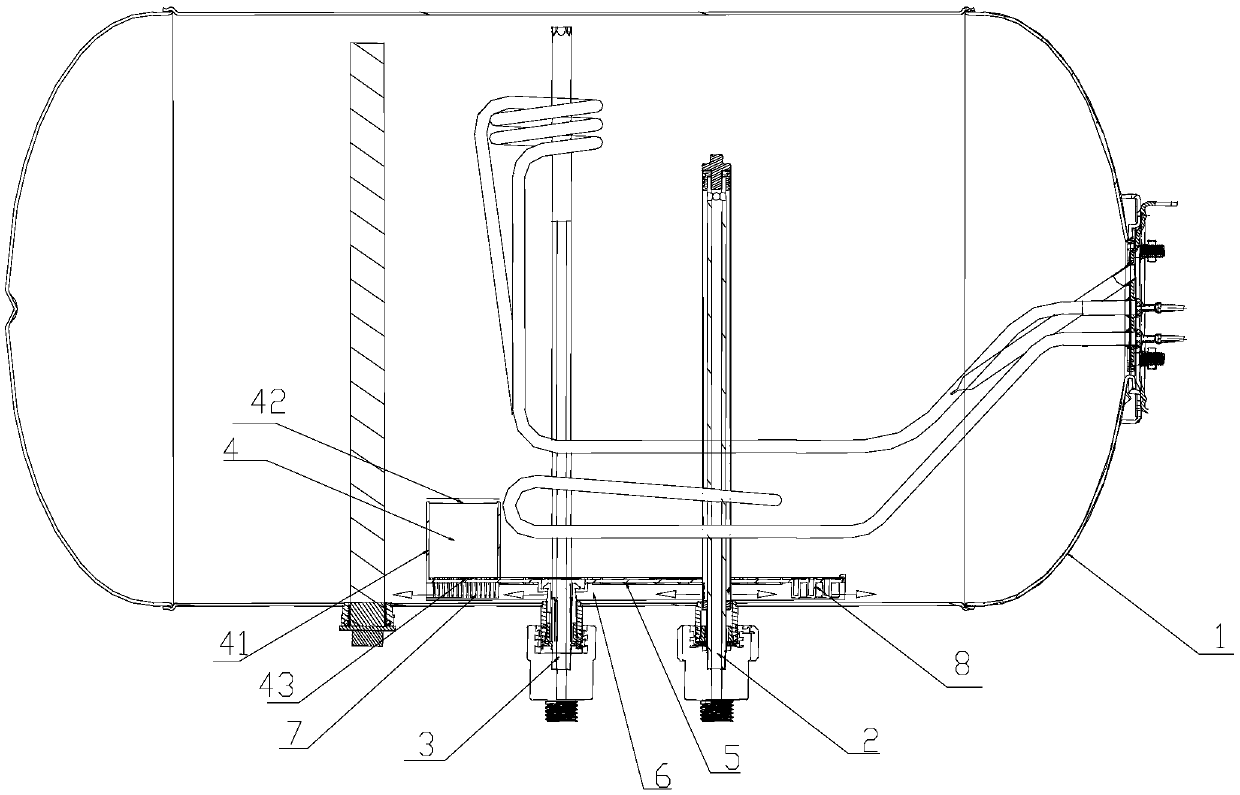
[0044] Such as figure 1 The water heater shown includes an inner tank 1 and a water inlet pipe 2. The water inlet pipe 2 is arranged in the inner tank 1, and further includes: Figure 2-6 As shown in the scale inhibition device, the scale inhibition device is located in the inner tank 1 and is arranged on the water inlet pipe 2. The scale inhibition device includes a containing chamber 4 containing a scale inhibitor, and the containing chamber 4 The scale inhibitor is dissolved and mixed with the water flowing out of the water inlet pipe 2 and then enters the inner tank 1.
[0045] The scale inhibition device can be installed on the water outlet end of the water inlet pipe 2, or on the body of the water inlet pipe 2. When installed on the body of the water inlet pipe 2, the water inlet pipe 2 and the scale inhibition device are connected, That is, all or part of the water in the water inlet pipe 2 will flow into the scale inhibitor. The scale inhibitor contained in the accommodating chamber 4 is a granular solid filter material. After being soaked in water, a scale inhibitor is generated, and the saturation concentration of the scale inhibitor in the water is lower than 3 mg/L. The scale inhibitor is installed in the inner tank 1, which does not occupy the external space; the scale inhibition principle that the solid granular scale inhibitor is dissolved to produce the scale inhibition factor to avoid blocking the water inlet pipe 2; at the same time, the solubility of the scale inhibitor is low and saturated Low concentration, long service life, eliminating the trouble of frequently replacing or adding scale inhibitors. The anti-scaling device is arranged on the water inlet pipe 2, and all/part of the water flowing out of the water inlet pipe 2 is heated after being heated by the anti-scaling device to reduce or even not produce scale.
[0046] Further, the scale inhibitor also includes such as Figure 7 As shown in the baffle 5, the baffle 5 is arranged at the bottom of the liner 1, and a water channel 6 is provided between the baffle 5 and the bottom of the liner 1, and the water channel 6 can be directly connected from the water inlet pipe 2 and the bottom of the liner 1 To form a channel, a special channel can also be provided between the baffle 5 and the bottom of the inner tank 1. At this time, the baffle 5 is a part of the water channel 6 and the water channel 6 is provided at the bottom of the inner tank 1. The water inlet pipe 2 communicates with the water channel 6, the containing chamber 4 is arranged on the baffle 5, and the water flow enters the water channel 6 from the water inlet pipe 2 and mixes with the scale inhibitor dissolved in the containing chamber 4 to enter the inner tank 1.
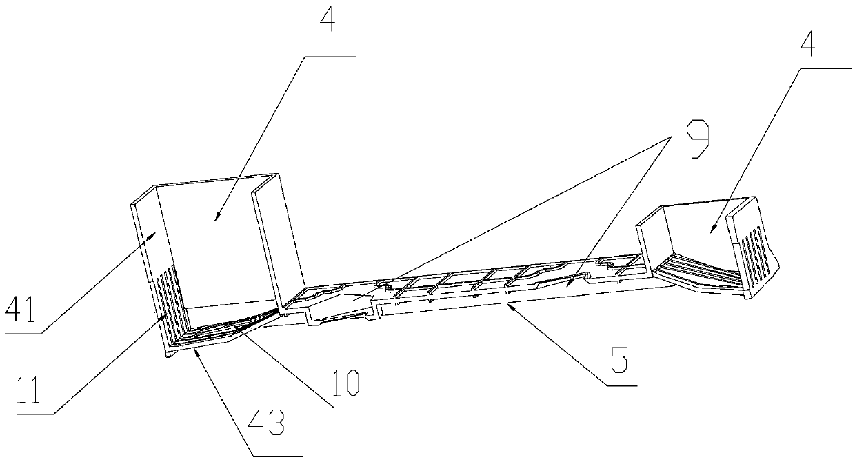
[0047] By arranging the baffle 5 in the water channel 6, the water flow direction can be improved, the temperature distribution inside the inner tank 1 can be more regular, and the hot water output rate can be improved. The accommodating chamber 4 is arranged at any position of the baffle 5, and the number of accommodating chambers 4 is at least one. Preferably, the number of accommodating chambers 4 is two, such as figure 2 , Image 6 As shown, and the two containing chambers 4 are located at both ends of the baffle 5, water outlets can be set at both ends of the water channel 6 at this time, and the water flowing out from the water inlet pipe 2 enters the water channel 6 and flows into the inner tank 1 through the water outlets at both ends Or the side wall of the containing chamber 4 is provided with a communication hole through which the water flows out, and the water in the water channel 6 enters the containing chamber 4 and then flows out into the inner tank 1 through the communicating hole on the side 41 of the containing chamber 4.
[0048] Further, the baffle 5 is arranged at the bottom of the inner container 1 in a direction parallel to the inner container 1. Since the scale inhibitor can be arranged on the water outlet end of the inlet pipe 2 or on the body of the inlet pipe 2, correspondingly, The baffle 5 can also be arranged at the water outlet end of the water inlet pipe 2 or on the body of the water inlet pipe 2. When the baffle 5 is arranged at the water outlet end of the water inlet pipe 2, the water outlet end of the water inlet pipe 2 is located in the water channel 6 at the bottom of the baffle 5 When the baffle 5 is arranged on the body of the water inlet pipe 2, an opening 9 is provided on the baffle 5, and the water inlet pipe 2 passes through the opening 9 and is set in the inner tank 1 and communicates with the water channel 6, The accommodating chamber 4 is arranged on one side/two sides of the baffle 5 of the water inlet pipe 2. When the anti-scaling device is installed on the body of the water inlet pipe 2, an opening 9 is provided on the baffle 5, and the water inlet pipe 2 passes through the opening 9 on the baffle 5, and there is a gap between the water inlet pipe 2 and the water channel 6 at the bottom of the baffle 5 If the water inlet pipe 2 and the water channels 6 communicate with each other, those skilled in the art can conceivably communicate with each other. Preferably, the water inlet pipe 2 is located in the water channel 6 through perforations or gaps. Since the inner tank 1 is also provided with a water outlet pipe 3, two openings 9 can be provided on the baffle 5, such as Figure 7 As shown, at this time, both the inlet pipe 2 and the outlet pipe 3 pass through the opening 9 on the baffle 5, the inlet pipe 2 communicates with the water channel 6 under the baffle 5, and the outlet pipe 3 and the water channel 6 under the baffle 5 are not connected. The cold water flows from the water inlet pipe 2 through the water channel 6 under the baffle 5 and enters the inner tank 1 after being mixed with the dissolved scale inhibitor.
[0049] Further, such as Figure 1-6 As shown, the containing chamber 4 includes a main body and an upper cover 42, the main body is composed of a bottom surface 43 and side surfaces 41 surrounding the bottom surface 43. When the bottom surface 43 is a plane, the bottom surface 43 is a part of the baffle 5. When the bottom surface 43 is an inclined surface, the bottom surface 43 is different from the baffle 5, and can be arranged on the baffle 5 and communicated with the baffle 5. The containing chamber 4 is a device capable of accommodating objects that can be imagined by those skilled in the art This embodiment does not impose further restrictions on its shape. The bottom surface 43 of the accommodating chamber 4 is provided with a number of first communication holes 10. When the bottom surface 43 is flat, the first communication hole 10 is provided in the accommodating chamber. On the baffle 5 of the chamber 4, such as Figure 7 Shown. Preferably, the size of the first communication hole 10 is smaller than the size of the scale inhibitor to prevent the granular scale inhibitor from escaping from the containing chamber 4 into the water channel 6. More preferably, the shape of the first communication hole 10 is Round, oval or long strip. The purpose of providing the first communication hole 10 is to connect the accommodating chamber 4 with the water channel 6, and after the water in the water channel 6 enters the accommodating chamber 4, the scale inhibitor contained in the accommodating chamber 4 dissolves the scale inhibitor produced by passing through the first A communicating hole 10 enters the inner tank 1 along with the water flow in the water channel 6.
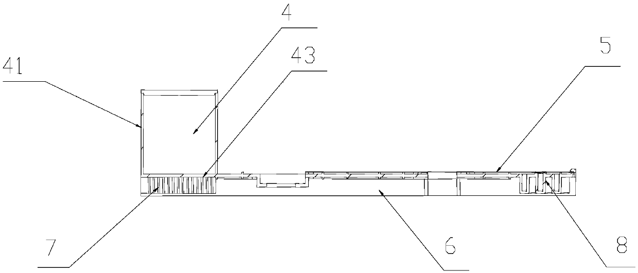
[0050] Such as figure 1 , image 3 As shown, the water channel 6 below the bottom surface 43 of the containing chamber 4 is provided with a plurality of first small channels 7 communicating with the containing chamber 4, and one end of the plurality of first small channels 7 is connected to the bottom surface 43 of the containing chamber 4. The other end is suspended at the bottom of the inner tank 1 and/or connected to the bottom of the inner tank 1; a second communication hole is provided on the side wall and/or bottom of the first small channel 7, which can dissolve the scale inhibitor on the one hand The scale inhibitor produced later enters the small channel from the containing chamber 4 with the water flow, and then flows out of the second communication hole on the small channel into the water channel 6, and finally flows into the inner tank 1 with the water flow of the water channel 6. The size of the second communication hole is smaller than the size of the scale inhibitor to prevent the granular scale inhibitor from entering the water channel 6; preferably, the plurality of first small channels 7 are evenly arranged on the bottom surface 43 of the containing chamber 4 at intervals, and Suspended at the bottom of the inner liner 1, a number of second communication holes are arranged on the bottom and/or side walls of the first small channels 7; preferably, the first small channels 7 are evenly arranged in the containing chamber at intervals The bottom surface 43 of 4 is connected with the bottom of the inner tank 1, and the side walls of the first small channels 7 are provided with a number of second communication holes, and the size of the second communication holes is smaller than the size of the scale inhibitor. In this embodiment, one end/two ends of the water channel 6 may be provided with water outlets, and the water flows through the second communication hole at the bottom and/or side wall of the first small channel 7 and the gaps between the first small channels 7 Enter the inner tank 1 through the outlet of the water channel 6.
[0051] The containing chamber 4 is divided into a water inlet chamber and a water outlet chamber, and the scale inhibitor is contained in any chamber. Preferably, the scale inhibitor is contained in the water inlet chamber. A communication part is also provided between the water inlet chamber and the water outlet chamber, and the communication part communicates the water inlet chamber and the water outlet chamber.
[0052] One embodiment is: the water inlet chamber and the water outlet chamber are separated from the top and bottom of the containing chamber 4, the lower part of the containing chamber 4 is the water inlet chamber, the upper part is the water outlet chamber, and the scale inhibitor is contained in the lower part. In the water chamber, the communication portion provided between the water inlet chamber and the water outlet chamber is a communication hole, a gap, or other methods that can be imagined by those skilled in the body art to connect the two chambers. The peripheral side 41 of the containing chamber 4 is divided into upper and lower parts. The upper side 41 of the containing chamber 4 is the side 41 of the water outlet chamber, and the lower side 41 of the containing chamber 4 is the side 41 of the water inlet chamber. In addition, the side 41 of the containing chamber 4 away from the water inlet pipe 2 extends to the bottom of the liner 1 and is in contact with the bottom of the liner 1, and at the same time, a communication hole is provided on the side 41 of the water outlet chamber to allow water flow to flow out of the water outlet chamber. In this way, all the water in the water channel 6 can pass through the water inlet chamber and then flow into the inner tank 1 through the water outlet chamber.
[0053] Another implementation is, such as Figure 4 As shown, the water inlet chamber and the water outlet chamber are separated left and right by partitions 12 arranged in the containing chamber 4, the chamber close to the water inlet pipe 2 is the water inlet chamber, and the chamber far away from the water inlet pipe 2 is the water outlet In the chamber, the partition 12 is perpendicular to the bottom surface 43 of the containing chamber 4 and extends downward from the bottom surface 43 of the containing chamber 4 in the vertical direction to be connected to the bottom of the inner tank 1 so that the water in the water channel 6 flows through the water channel 6 After entering the water inlet chamber, it flows into the water channel 6 through the water outlet chamber. The height of the partition 12 is less than or equal to the height of the containing chamber 4; at this time, the partition 12 divides the bottom surface 43 of the containing chamber 4 into two parts, one part belongs to the bottom surface 43 of the water inlet chamber, and the other part belongs to The bottom surface 43 of the water outlet chamber, and the bottom surface 43 of the water inlet chamber and the bottom surface 43 of the water outlet chamber have first communication holes 10.
[0054] Preferably, the height of the partition plate 12 is smaller than the height of the accommodating chamber 4, and between the top end of the partition plate 12 and the upper cover 42 of the accommodating chamber 4 is formed a connection between the water inlet chamber and the water outlet chamber. In the communicating part, the scale inhibitor is arranged in the water inlet chamber; at this time, the water in the water channel 6 flows into the water inlet chamber through the first communication hole 10 on the bottom surface 43 of the water inlet chamber, and then passes through the top of the partition plate 12 and The communication part between the upper cover 42 enters the water outlet chamber, and finally flows out from the first communication hole 10 on the bottom surface 43 of the water outlet chamber into the water channel 6 and enters the inner tank 1.
[0055] Preferably, the height of the partition 12 is equal to the height of the accommodating chamber 4, and the top end of the partition 12 is connected to the upper cover 42 of the accommodating chamber 4, and the communicating part is a water inlet provided on the upper part of the partition 12 A number of third communication holes communicated between the chamber and the water outlet chamber, the scale inhibitor is arranged in the water inlet chamber, and the size of the third communication hole is smaller than the size of the scale inhibitor. At this time, the water in the water channel 6 flows into the water inlet chamber through the first communication hole 10 on the bottom surface 43 of the water inlet chamber, and then enters the water outlet chamber through the third communication hole on the upper part of the partition plate 12, and finally from the water outlet chamber The first communication hole 10 on the bottom surface 43 of the device flows out into the water channel 6 and finally enters the inner tank 1 from the water channel 6.
[0056] Such as figure 2 , 5 As shown in 6, the bottom surface 43 of the accommodating chamber 4 is arranged obliquely, which increases the contact area between the scale inhibitor and the water flow, so that the scale inhibitor can be more fully mixed with water after being dissolved. The inclination manner of the bottom surface 43 in this embodiment is an oblique arrangement manner of the bottom surface 43 conceivable by those skilled in the art. Preferably, the bottom surface 43 of the containing chamber 4 changes from the side 41 close to the water inlet pipe 2 to the side 41 far away from the water inlet pipe 2 Inclined to form an inclined surface with a certain arc; the side 41 of the containing chamber 4 away from the water inlet pipe 2 extends downward to connect with the bottom of the inner tank 1, thereby blocking the water at the bottom of the containing chamber 4 from flowing into the inner tank 1 from the water channel 6, and A number of fourth communicating holes 11 are also provided on this side surface 41. The size of the fourth communicating holes 11 is smaller than the size of the scale inhibitor. The water at the bottom of the containing chamber 4 passes through the first communicating holes on the bottom surface 43 of the containing chamber 4. 10 enters the accommodating chamber 4, mixes with the scale inhibitor dissolved in the accommodating chamber 4, and flows into the inner liner 1 through the fourth communication hole 11 on the side 41. The height of the plurality of fourth communication holes 11 is lower than the height of the containing chamber 4.
[0057] Such as figure 1 , 3 5, when only the baffle 5 on one side of the water inlet pipe 2 is provided with a containing chamber 4, the water channel 6 below the baffle 5 on the other side where the containing chamber 4 is not provided is provided with a number of second The small channel 8, the second small channel 8 is arranged to disperse the water flow, so that the water in the water channel 6 flows as much as possible toward the end where the receiving chamber 4 is provided, but at the same time, it can also make the water flow in the water channel 6 By entering the inner tank 1, the efficiency of cold water inlet is improved. The plurality of second small channels 8 communicate with the upper space of the baffle 5, one end of the plurality of second small channels 8 is connected with the lower surface of the baffle 5, and the other end is suspended at the bottom of the inner tank 1 and/or connected with the bottom of the inner tank 1 Preferably, the plurality of second small channels 8 are evenly arranged at intervals on the lower surface of the other side baffle 5 where the receiving chamber 4 is not provided, and suspended above the bottom of the inner liner 1, in the plurality of second small channels The bottom and/or side walls of the channel 8 are provided with a number of fifth communication holes; preferably, the plurality of second small channels 8 are evenly arranged at intervals on the lower surface of the baffle 5 on the other side where the receiving chamber 4 is not provided. Connected to the bottom of the inner liner 1, a plurality of fifth communication holes are provided on the side walls of the plurality of second small channels 8. Although this embodiment cannot completely prevent the generation of scale, it can reduce the generation of scale to a large extent, and at the same time, it does not affect the cold water entering the inner tank 1. Further, such as Figure 7 As shown, a number of sixth communication holes 13 are provided on the baffle 5 on the other side of the baffle 5 where the receiving chamber 4 is not provided, and the small channel communicates with the upper space of the baffle 5 through the sixth communication hole 13; preferably, the The shape of the sixth communication hole 13 is circular, elliptical or elongated. In this embodiment, water outlets may be provided at one end/two ends of the water channel 6, and the water flow passes through the bottom and/or side of the second small channel 8. The fifth communication hole of the wall and the gap between the second small channels 8 enter the inner tank 1 from above the baffle 5 or the water outlet of the water channel 6.
[0058] Such as figure 2 , 6 As shown, the baffles 5 on both sides of the water inlet pipe 2 are provided with containment chambers 4, preferably two containment chambers 4 are provided at both ends of the baffle 5. The two containing chambers 4 have the same or different sizes, and/or the same or different shapes, and/or the same or different internal structures.
[0059] The above are only the preferred embodiments of the present invention, and do not limit the present invention in any form. Although the present invention has been disclosed as the preferred embodiments, it is not intended to limit the present invention. Any technology familiar with this patent Without departing from the scope of the technical solution of the present invention, personnel can use the technical content suggested above to make slight changes or modification into equivalent embodiments with equivalent changes, but any content that does not depart from the technical solution of the present invention is based on the technology of the present invention Essentially, any simple modifications, equivalent changes and modifications made to the above embodiments still fall within the scope of the present invention.

PUM

no PUM

Description & Claims & Application Information

We can also present the details of the Description, Claims and Application information to help users get a comprehensive understanding of the technical details of the patent, such as background art, summary of invention, brief description of drawings, description of embodiments, and other original content. On the other hand, users can also determine the specific scope of protection of the technology through the list of claims; as well as understand the changes in the life cycle of the technology with the presentation of the patent timeline. Login to view more.

Similar technology patents

Universal joint communicating pipe

PendingCN114183625AAvoid cloggingImprove water flowAdjustable jointsPipe units with cleaning aperturesEngineeringMechanics
Owner:王蕊

Pressure-stabilizing type inner spiral plastic pipe for building drainage vertical pipe

InactiveCN110886910AImprove water flowSmall pressure fluctuationsPipe elementsRigid pipesDrainage flowEnvironmental geology
Owner:宁夏迈尖管道科技有限公司

Shaft type pump device with annular water inlet groove

InactiveCN107587601AImprove water flowReduce hydraulic lossSewerage structuresControl engineeringHydraulic engineering
Owner:YANGZHOU UNIV

Sewage treatment unit capable of effectively reducing COD suspended solids (SS)

InactiveCN105169775AIncrease water outputImprove water flowFiltration separationSewageSewage treatment
Owner:ZHEJIANG JINGANG TEXTILE PRINTING & DYEING

Outflow optimization device of pontoon type water-lifting aerator

InactiveCN104445657AImprove water flowAvoid fatigue damageWater aerationSustainable biological treatmentBell mouthEnergy loss
Owner:XI'AN UNIVERSITY OF ARCHITECTURE AND TECHNOLOGY

Classification and recommendation of technical efficacy words

  • Improve water flow

Large-volume three-dimensional circulating aquaculture system

InactiveCN102090353AImprove space utilization and nutrient utilizationImprove water flowClimate change adaptationPisciculture and aquariaBiologyBiological membrane
Owner:SHANGHAI OCEAN UNIV

Core-loosing highly effective energy-conserving vertical diagonal flow pump

InactiveCN101418814AImprove water flowReduce hydraulic lossPump componentsPumpsImpellerEffective energy
Owner:利欧集团湖南泵业有限公司

Outflow optimization device of pontoon type water-lifting aerator

InactiveCN104445657AImprove water flowAvoid fatigue damageWater aerationSustainable biological treatmentBell mouthEnergy loss
Owner:XI'AN UNIVERSITY OF ARCHITECTURE AND TECHNOLOGY
Why Eureka
Try Eureka