Shaft type pump device with annular water inlet groove

A technology of water inlet trough and pump device, which is applied to water supply devices, waterway systems, drainage structures, etc., can solve the problems of poor water inlet conditions, turbulence, and easy formation of vortices of impellers, so as to reduce hydraulic loss, improve water inlet flow state, reduce The effect of energy consumption

Inactive Publication Date: 2018-01-16
YANGZHOU UNIV
5 Cites 0 Cited by

AI-Extracted Technical Summary

Problems solved by technology

However, in this wellbore water inlet form, the water flow is often turbulent when it enters the well from t...

Method used

After crossbeam is made, be fixed on the shaft wall. After the crossbeam is installed, the water homogenizer can be hoist...

Abstract

The invention discloses a shaft type pump device with an annular water inlet groove, and belongs to the technical field of hydraulic engineering. The shaft type pump device comprises a shaft, a pump section, a horn pipe, a water outlet pipe and a water inlet pipe, and is characterized in that a water distributing vessel is arranged and located above guide blades, the bottom of the inner wall of the water distributing vessel is flush with the bottom of the inner wall of the water inlet pipe, the top of the water distributing vessel is flush with the top of the inner wall of the water inlet pipe, the clear weight is equal to the diameter of the water inlet pipe, the water distributing vessel is directly connected with the water inlet pipe, and water flows into the water distributing vessel through the water inlet pipe and reaches an inlet of the horn pipe of the water pump through a water inlet groove. The pump device is suitable for various shaft type water inlet modes, the formation ofvortexes can be reduced to make the water flow more smoothly, the overall performance of the pump device is obviously improved, the energy is saved, and the consumption is reduced.

Application Domain

Technology Topic

Control engineeringHydraulic engineering +1

Image

  • Shaft type pump device with annular water inlet groove
  • Shaft type pump device with annular water inlet groove
  • Shaft type pump device with annular water inlet groove

Examples

  • Experimental program(1)

Example Embodiment

[0022] The invention is suitable for wellbore pump devices, and the drawing is designed according to the design requirements.
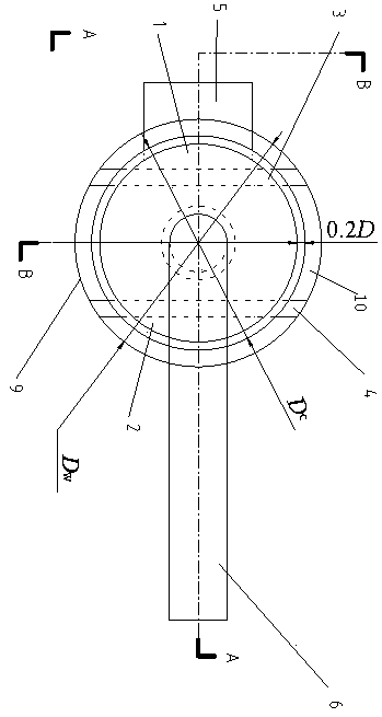
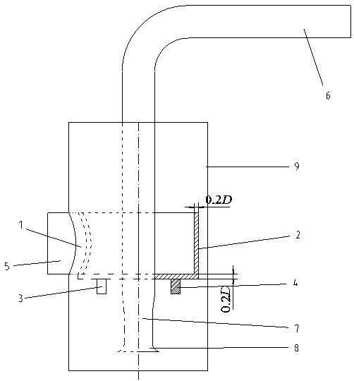
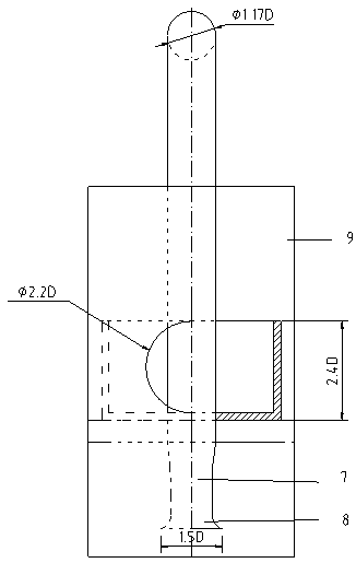
[0023] A well bore pump device with a ring-shaped water inlet groove includes a water inlet pipe 5, a water outlet pipe 6, a pump section 7, a horn tube 8, and a well bore 9, and a water homogenizing dish is arranged in the well.
[0024] For ease of installation, the homogenizing dish is divided into two halves, namely the homogenizing dish 1 on the inlet side and the homogenizing dish 2 on the outlet side. The shapes are symmetrical. The inlet pipe 5 is connected to the homogenizing dish 1 on the inlet side so that the water can flow from The water inlet pipe enters the homogenizing dish, and then overflows from the top of the homogenizing dish, flows into the annular water inlet tank 10, and reaches the entrance of the horn tube. The thickness of the bottom plate and the side wall of the uniform water dish are both 0.2D, and the net height is equal to the diameter of the inlet pipe. The outer diameter and the width of the inlet groove are based on the area of ​​the inlet groove and the diameter of the wellbore. D W The calculation confirms that the bottom of the inner wall of the homogenizing vessel is flush with the bottom of the inner wall of the water inlet pipe.
[0025] Under the water inlet side uniform water dish 1 and the outlet water side uniform water dish 2, respectively, a water inlet side beam 3 and a water outlet side beam 4 are provided for support. The beam can be made of I-beam or channel steel to meet the rigidity requirements.
[0026] After the beam is finished, it is fixed on the shaft wall. After the beam is installed, the homogenizing vessel can be hoisted into the well and fixed on the beam with bolts. The hoisting ring is reserved to facilitate future hoisting and maintenance.
[0027] The material of the homogenizing dish can be lighter materials such as aluminum alloy or materials such as glass steel.
[0028] The homogenizing dish is set up so that the water flows through the water inlet pipe to the homogenizing dish, and then flows into the water inlet tank from the periphery of the homogenizing dish in the form of overflow, and then enters the inlet of the pump bell pipe to achieve the goal of making the water flow even and smooth. Minimize the generation of vortex and improve the uniformity of water flow, thereby improving the uniformity of flow velocity at the impeller inlet. Therefore, the hydraulic loss in the wellbore will be reduced, and the efficiency of the pumping device will increase accordingly. The invention is suitable for various pump devices adopting wellbore water intake, can reduce the formation of vortex, make the water flow smoother, significantly improve the overall performance of the pump device, save energy and reduce consumption.

PUM

no PUM

Description & Claims & Application Information

We can also present the details of the Description, Claims and Application information to help users get a comprehensive understanding of the technical details of the patent, such as background art, summary of invention, brief description of drawings, description of embodiments, and other original content. On the other hand, users can also determine the specific scope of protection of the technology through the list of claims; as well as understand the changes in the life cycle of the technology with the presentation of the patent timeline. Login to view more.

Similar technology patents

Universal joint communicating pipe

PendingCN114183625AAvoid cloggingImprove water flowAdjustable jointsPipe units with cleaning aperturesEngineeringMechanics
Owner:王蕊

Pressure-stabilizing type inner spiral plastic pipe for building drainage vertical pipe

InactiveCN110886910AImprove water flowSmall pressure fluctuationsPipe elementsRigid pipesDrainage flowEnvironmental geology
Owner:宁夏迈尖管道科技有限公司

Water heater

ActiveCN110966751AImprove water flowLow volume saturationWater heatersMechanical engineeringWater heater
Owner:QINGDAO ECONOMIC & TECHN DEV ZONE HAIER WATER HEATER

Sewage treatment unit capable of effectively reducing COD suspended solids (SS)

InactiveCN105169775AIncrease water outputImprove water flowFiltration separationSewageSewage treatment
Owner:ZHEJIANG JINGANG TEXTILE PRINTING & DYEING

Outflow optimization device of pontoon type water-lifting aerator

InactiveCN104445657AImprove water flowAvoid fatigue damageWater aerationSustainable biological treatmentBell mouthEnergy loss
Owner:XI'AN UNIVERSITY OF ARCHITECTURE AND TECHNOLOGY

Classification and recommendation of technical efficacy words

  • Improve water flow
  • Reduce hydraulic loss

Large-volume three-dimensional circulating aquaculture system

InactiveCN102090353AImprove space utilization and nutrient utilizationImprove water flowClimate change adaptationPisciculture and aquariaBiologyBiological membrane
Owner:SHANGHAI OCEAN UNIV

Core-loosing highly effective energy-conserving vertical diagonal flow pump

InactiveCN101418814AImprove water flowReduce hydraulic lossPump componentsPumpsImpellerEffective energy
Owner:利欧集团湖南泵业有限公司

Outflow optimization device of pontoon type water-lifting aerator

InactiveCN104445657AImprove water flowAvoid fatigue damageWater aerationSustainable biological treatmentBell mouthEnergy loss
Owner:XI'AN UNIVERSITY OF ARCHITECTURE AND TECHNOLOGY

Method for designing centrifugal impeller splitter blade

InactiveCN105971931AImprove speed distributionReduce hydraulic lossPump componentsPumpsImpellerFront cover
Owner:JIANGSU UNIV

Electric watering spray gun

PendingCN106914355AReduce hydraulic lossEnsure water impactMovable spraying apparatusEngineeringWater spray
Owner:NINGBO SHENGDA SUNSHINE AUTOMATION TECH CO LTD

Core-loosing highly effective energy-conserving vertical diagonal flow pump

InactiveCN101418814AImprove water flowReduce hydraulic lossPump componentsPumpsImpellerEffective energy
Owner:利欧集团湖南泵业有限公司

Impeller of hydraulic turbine

Owner:LANSHEN GRP CORP LTD +1
Why Eureka
Try Eureka