A differential pressure flowmeter in a waste water pipeline

A flow meter and differential pressure technology, applied in the field of differential pressure flow meters, can solve the problems of easy scratching and damage to the display screen, easy accumulation of dirt in the pipeline, affecting the measurement accuracy, etc.

Active Publication Date: 2021-04-06
谈格
View PDF13 Cites 0 Cited by
  • Summary
  • Abstract
  • Description
  • Claims
  • Application Information

AI Technical Summary

Problems solved by technology

[0002] The differential pressure flowmeter is an instrument for measuring the flow rate. It utilizes the principle that there is a certain relationship between the pressure difference and the flow rate generated when the fluid flows through the throttling device. The flow measurement and throttling are realized by measuring the pressure difference. The device is a local contraction element installed in the pipeline. The most commonly used ones are orifice plates, nozzles and Venturi tubes. In wastewater pipelines, differential pressure flowmeters are usually installed to measure the flow of wastewater, but in use There are disadvantages at this time. First, the pressure guiding tube is easy to be damaged by collision and deformation, which affects the measurement accuracy. Second, the display screen of the instrument is easy to be scratched and damaged. In addition, during the transportation process, the rear end of the main part of the flowmeter is easily damaged by collision with the ground. Finally, , used in waste water pipes, dirt is easy to accumulate in the pipes, which will affect the measurement accuracy. Therefore, we propose a differential pressure flowmeter in waste water pipes

Method used


Image

  • A differential pressure flowmeter in a waste water pipeline
  • A differential pressure flowmeter in a waste water pipeline
  • A differential pressure flowmeter in a waste water pipeline

Examples


Embodiment Construction

[0028] The following will clearly and completely describe the technical solutions in the embodiments of the present invention with reference to the accompanying drawings in the embodiments of the present invention. Obviously, the described embodiments are only some, not all, embodiments of the present invention. Based on the embodiments of the present invention, all other embodiments obtained by persons of ordinary skill in the art without making creative efforts belong to the protection scope of the present invention.

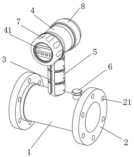
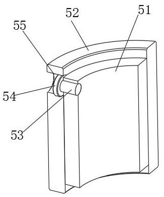
[0029] see Figure 1-6 , a differential pressure flowmeter in a wastewater pipeline, comprising a pipe body 1, a pressure guide tube 3 is arranged on the outer surface of the upper end of the pipe body 1, the lower end of the pressure guide tube 3 extends to the inner side of the pipe body 1, and the pressure guide tube 3 is fixedly connected to the pipe body 1, the outer surface of the pressure guiding tube 3 is provided with a buffer structure 5, the upper e...


PUM


Abstract

The invention relates to the field of differential pressure flowmeters, and discloses a differential pressure flowmeter in a waste water pipeline, which includes a pipe body, the outer surface of the upper end of the pipe body is provided with a pressure guiding tube, and the lower end of the pressure guiding tube Extending to the inner side of the pipe body, and the pressure guiding tube is fixedly connected with the tube body, the outer surface of the pressure guiding tube is provided with a buffer structure, the upper end of the pressure guiding tube is connected to the main body of the flowmeter, and the flowmeter The front end of the main body is movably equipped with a protective structure, the rear end of the flowmeter main body is provided with an anti-collision structure, and the outer surface of the upper end of the pipe body is provided with a dredging structure on the side close to the pressure guiding tube. The differential pressure flowmeter in the waste water pipeline has the advantages that the pressure guide tube is not easy to be damaged, the instrument panel is not easy to be scratched, plays a good protective role during the transportation process, and is easy to clean the dirt accumulated in the pipe body.

Description

technical field [0001] The invention relates to the field of differential pressure flowmeters, in particular to a differential pressure flowmeter in a waste water pipeline. Background technique [0002] The differential pressure flowmeter is an instrument for measuring the flow rate. It utilizes the principle that there is a certain relationship between the pressure difference and the flow rate generated when the fluid flows through the throttling device. The flow measurement and throttling are realized by measuring the pressure difference. The device is a local contraction element installed in the pipeline. The most commonly used ones are orifice plates, nozzles and Venturi tubes. In wastewater pipelines, differential pressure flowmeters are usually installed to measure the flow of wastewater, but in use There are disadvantages at this time. First, the pressure guiding tube is easy to be damaged by collision and deformation, which affects the measurement accuracy. Second, t...

Claims


Application Information

Patent Timeline
Patent Type & Authority Patents(China)
IPC IPC(8): G01F1/36G01F15/00G01F15/18F16F15/02
CPCF16F15/02G01F1/36G01F15/00G01F15/18
Inventor 谈格吉春雷许杰吴加成
Owner 谈格
Why Eureka
Try Eureka