
Spoiler transfer working position apparatus

Inactive Publication Date: 2020-12-04
湖北鹏良工贸股份有限公司
View PDF1 Cites 0 Cited by
  • Summary
  • Abstract
  • Description
  • Claims
  • Application Information

AI Technical Summary

Problems solved by technology

[0006] In order to solve the above technical problems, the present invention provides a spoiler transfer tool to solve the problem of inserting the spoilers into the reserved slots one by one by aligning the holes when putting the spoiler into the transfer device. It is very troublesome, and the spoiler in the transfer device is placed in layers, it is very inconvenient to take the spoiler, the steps are cumbersome, and the practicability is not high.

Method used


Image

  • Spoiler transfer working position apparatus
  • Spoiler transfer working position apparatus
  • Spoiler transfer working position apparatus

Examples


Embodiment

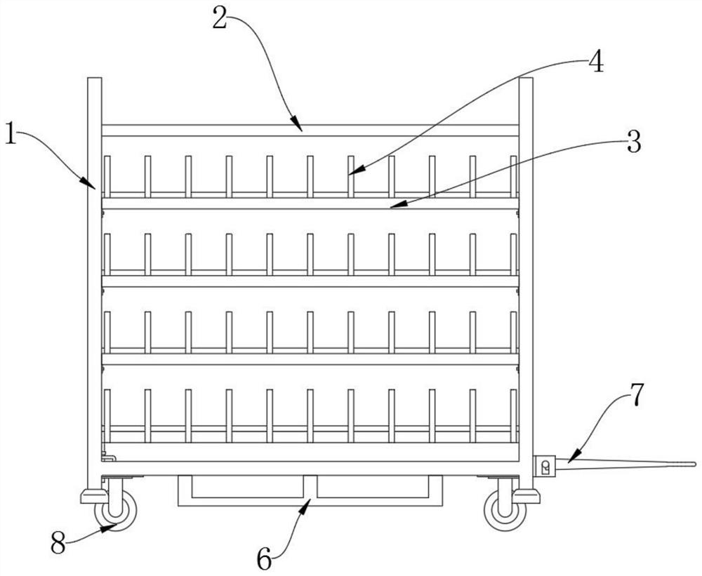
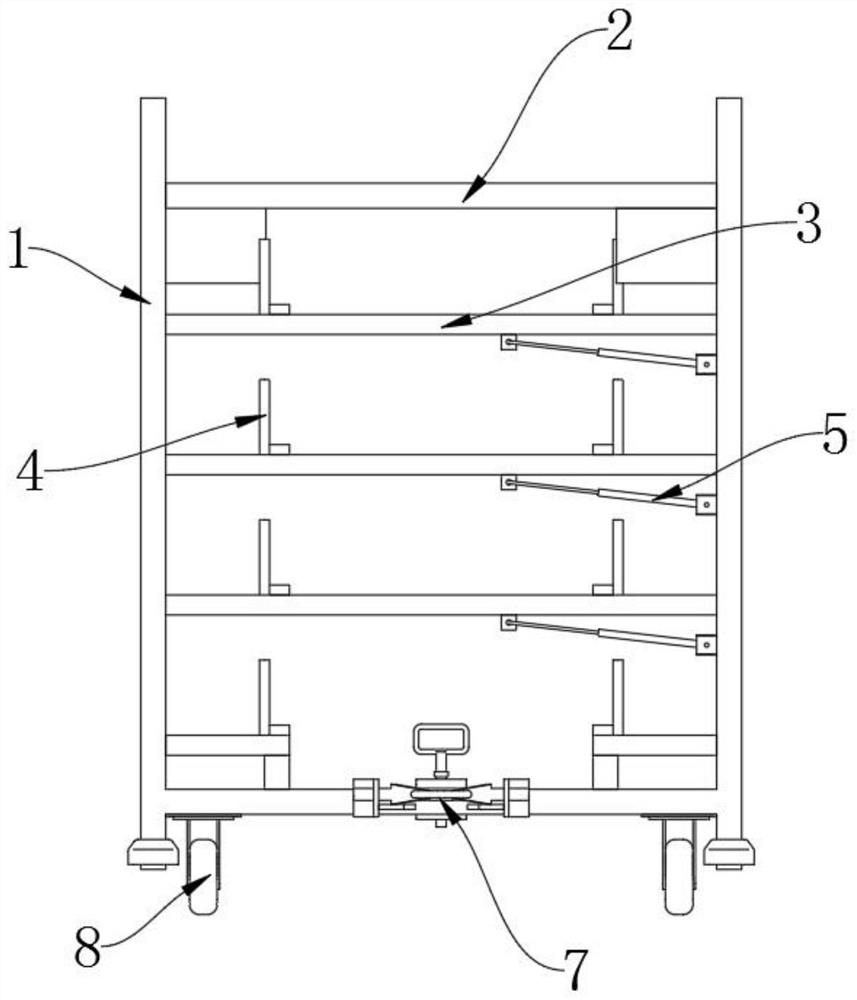
[0027] as attached figure 1 To attach Figure 4 Shown:

[0028] The invention provides a spoiler transfer station appliance, which includes a column frame 1, a flip frame 3, a separation rod 4, a pneumatic spring 5, a forklift carrying iron 6, a tractor 7 and a moving wheel 8; the top of the column frame 1 is fixedly connected with The top support frame 2; the flip frame 3 is plugged into the interior of the column frame 1; the flip frame 3 is provided with three groups, and the flip frames 3 are arranged in the interior of the column frame 1 from top to bottom, as attached figure 1 , attached figure 2 And attached image 3 As shown, the device can store the spoiler in an orderly manner, which improves the flexibility of the device; the divider bar 4 is fixedly connected to the inner cross bar of the flip frame 3 and the inner cross bar at the bottom of the column frame 1; the divider bar Both the rod body of 4 and the top of the flip frame 3 are equipped with a protectiv...


PUM


Abstract

The invention discloses a spoiler transfer working position apparatus, relates to the technical field of transfer apparatuses, and solves the problems that when spoilers are placed into a transfer apparatus in prior art, the spoilers need to be aligned with hole sites to be inserted into reserved grooves one by one, the operation is very troublesome, the spoilers in the transfer apparatus are placed in a layered manner, the spoilers at the bottom are very inconvenient to take, and steps are tedious. The spoiler transfer working position apparatus comprises a turnover frame; the turnover frameis inserted into a stand column frame. The turnover frame of the device can be turned over under the action of pneumatic springs, the turnover frame at the top can be turned up when the spoilers are placed, the spoilers are sequentially placed inside partition rods at the top of the turnover frame from bottom to top, and when the spoilers are taken, after the spoilers on the upper layer are taken,the turnover frame can be turned over again through the pneumatic springs, so that the spoilers on the lower layer are convenient to take.

Description

technical field [0001] The invention belongs to the technical field of transfer devices, and more specifically relates to a spoiler transfer station device. Background technique [0002] The spoiler can effectively reduce the air resistance generated when the vehicle is running at high speed, which not only saves fuel, but also improves the stability of the vehicle. At present, the spoiler that has been mass-produced in the factory needs to be transported by the transfer device. Turn to a suitable place to continue processing or transport for delivery. [0003] For example, in the patent with the application number: CN201922091574.5, a rear spoiler assembly is disclosed, including: a motor fixed on the vehicle body, a transmission rod driven by the motor to rotate, a connecting rod device driven by the transmission rod, and The spoiler connected with the connecting rod device; the connecting rod device includes: a fixed bracket fixed to the vehicle body, a spoiler connectin...

Claims


Application Information

Patent Timeline
Patent Type & Authority Applications(China)
IPC IPC(8): B65D6/08B65D25/02B65D25/52B65D81/05
CPCB65D7/14B65D11/14B65D25/02B65D25/52B65D81/05
Inventor 胡贵斌陈南荣万为超吴兴有毕磊
Owner 湖北鹏良工贸股份有限公司
Learn More