Game scene equipment and game scene method realized by holographic technology

A game scene and holographic technology technology, applied in the field of game scene equipment realized by holographic technology, can solve the problems of consuming a lot of human, material and financial resources, single model, loss of freshness, etc., to achieve low cost, strong experience, and diverse game modes. Effect

Inactive Publication Date: 2020-04-10
青岛元盛物联信息科技有限公司
View PDF5 Cites 0 Cited by
  • Summary
  • Abstract
  • Description
  • Claims
  • Application Information

AI Technical Summary

Problems solved by technology

But the built model is single and fixed, and loses its freshness for a long time
If the mod

Method used


Image

  • Game scene equipment and game scene method realized by holographic technology
  • Game scene equipment and game scene method realized by holographic technology

Examples


Example Embodiment

[0028] Example 1:

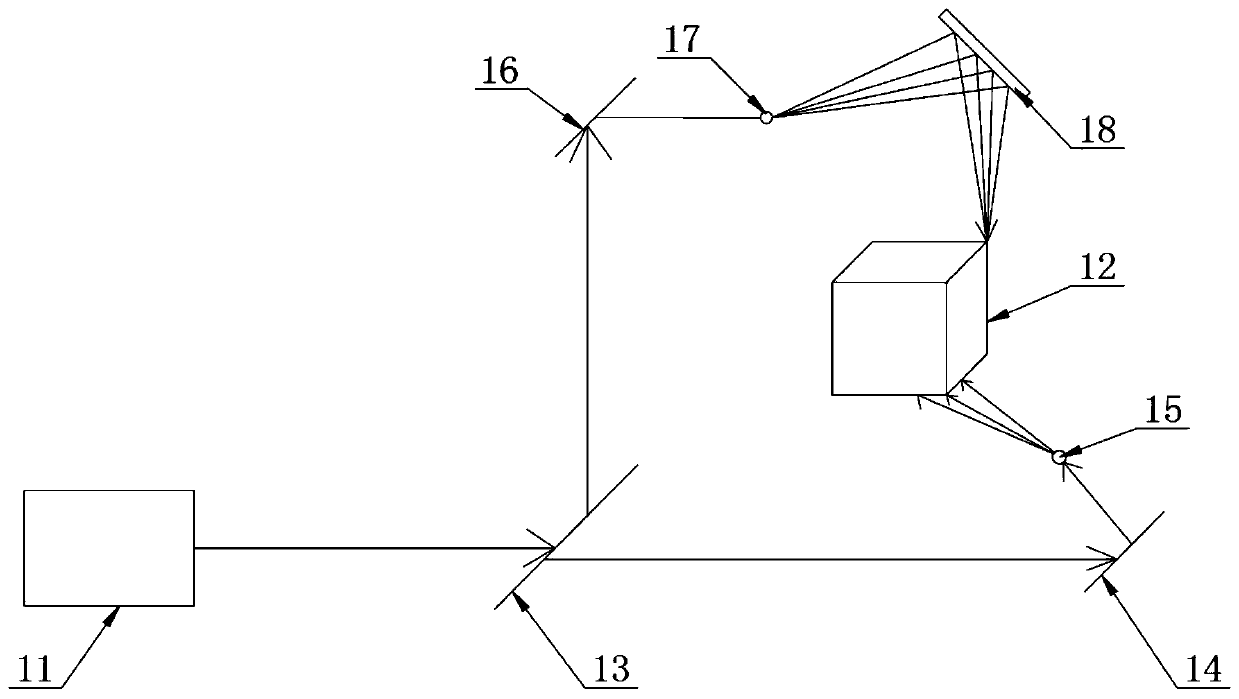
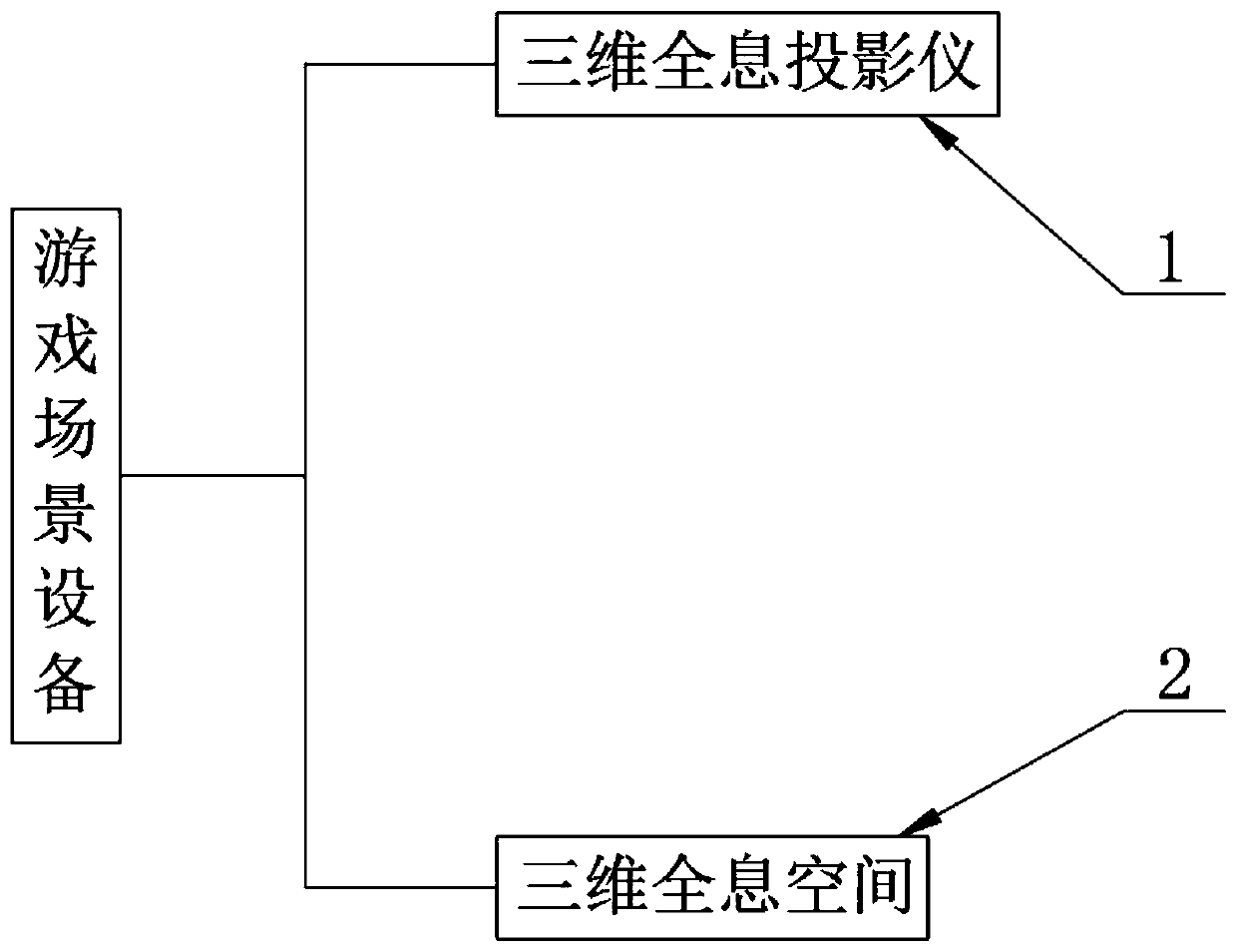
[0029] The present invention provides such as Figure 1-2 A game scene device realized by holographic technology as shown includes 3D holographic projector 1 and 3D holographic space 2. The resolution of 3D holographic projector 1 is set to 5000PPI, which can precisely control the brightness, color and angle of each beam;

[0030] The three-dimensional holographic projector 1 includes a laser transmitter 11 and an imaging object 12. The laser output end of the laser transmitter 11 is provided with a beam splitter 13, and the beam splitter 13 is provided with two laser beam splitting directions. One laser beam splitting direction of the beam splitter 13 is provided with a first plane mirror 14, another laser beam splitting direction of the beam splitter 13 is provided with a second plane mirror 16, and the light refraction direction of the first plane mirror 14 is provided with a second plane mirror 16. A beam expander 15, the second beam expander 17 is pro...

Example Embodiment

[0040] Example 2:

[0041] The present invention provides such as Figure 1-2 A game scene device realized by holographic technology as shown includes 3D holographic projector 1 and 3D holographic space 2. The resolution of 3D holographic projector 1 is set to 5000PPI, which can precisely control the brightness, color and angle of each beam;

[0042]The three-dimensional holographic projector 1 includes a laser transmitter 11 and an imaging object 12. The laser output end of the laser transmitter 11 is provided with a beam splitter 13, and the beam splitter 13 is provided with two laser beam splitting directions. One laser beam splitting direction of the beam splitter 13 is provided with a first plane mirror 14, another laser beam splitting direction of the beam splitter 13 is provided with a second plane mirror 16, and the light refraction direction of the first plane mirror 14 is provided with a second plane mirror 16. A beam expander 15, the second beam expander 17 is prov...


PUM


Abstract

The invention discloses game scene equipment and a game scene method realized by a holographic technology, and particularly relates to the field of application of the holographic technology in games,wherein the game scene equipment comprises a three-dimensional holographic projector and a three-dimensional holographic space; the three-dimensional holographic projector comprises a laser emitter and an imaging object; a beam splitter is arranged at the laser output end of the laser emitter; the beam splitter is provided with two laser beam splitting directions; a first plane mirror is arrangedin one laser beam splitting direction of the beam splitter, a second plane mirror is arranged in the other laser beam splitting direction of the beam splitter, a first beam expander is arranged in thelight refraction direction of the first plane mirror, and a second beam expander is arranged in the light refraction direction of the second plane mirror. According to the invention, through a technology of recording and reproducing a real three-dimensional image of an object by utilizing interference and diffraction principles, space 3D display can be randomly switched in one space, and the space is segmented, so that game experience of a player is richer.

Description

technical field [0001] The present invention relates to the technical field of application of holographic technology in games, and more specifically, the present invention relates to a game scene device and method realized by holographic technology. Background technique [0002] 3D games are games that use spatial three-dimensional computing technology to realize operations. From the perspective of programming implementation, the basic model of the game (game characters, scenes, and basic terrain) is realized using a three-dimensional model, and the character control of the game is realized using a three-dimensional programming algorithm, so this game is called 3D. game. D in 3D is the abbreviation of Dimension (dimension). The position of a point in a 3D game is determined by three coordinates (x, y, z). The objectively existing real space is a three-dimensional space, which has three dimensions: length, width, and height. Three-dimensional games (3D games are also call...

Claims


Application Information

Patent Timeline
IPC IPC(8): A63F13/52G03H1/22G06T17/00
CPCA63F13/52G06T17/00G03H1/2202A63F2300/66
Inventor 刘刚丁学伟肖丹妮
Owner 青岛元盛物联信息科技有限公司
Why Eureka
Try Eureka