Sludge discharging method of sedimentation tank

A sedimentation tank and sludge discharge pipe technology, which is applied in the direction of separation methods, sedimentation separation, chemical instruments and methods, etc., can solve the problems of deteriorating water quality of the sedimentation tank, damage to the normal operation of the sedimentation tank, and sludge floating, so as to achieve the complete sedimentation. Full, low equipment damage rate, low energy consumption effect

Pending Publication Date: 2020-04-10
SHENZHEN UNIVERSILICON ENVIRONMENTAL SCI & TECH CO LTD
View PDF14 Cites 3 Cited by
  • Summary
  • Abstract
  • Description
  • Claims
  • Application Information

AI Technical Summary

Problems solved by technology

[0002] Timely sludge discharge from the sedimentation tank is an extremely important task in the operation and management of the sedimentation tank. If the sludge is not discharged in time, anaerobic fermentation will occur, causing the sludge to float up, which not only destroys the normal operation of the sedimentation tank, but also affects the quality of the effluent of the sedimentation tank. deterioration

Method used


Image

  • Sludge discharging method of sedimentation tank
  • Sludge discharging method of sedimentation tank
  • Sludge discharging method of sedimentation tank

Examples


Embodiment Construction

[0038] In order to facilitate the understanding of the present invention, the present invention will be described more fully below with reference to the relevant drawings. The preferred embodiments of the present invention are shown in the drawings. However, the present invention can be implemented in many different forms and is not limited to the embodiments described herein. On the contrary, the purpose of providing these embodiments is to make the disclosure of the present invention more thorough and comprehensive.

[0039] It should be noted that when an element is referred to as being "fixed to" another element, it can be directly on the other element or a central element may also exist. When an element is considered to be "connected" to another element, it can be directly connected to the other element or an intermediate element may be present at the same time. The terms "vertical", "horizontal", "left", "right" and similar expressions used herein are for illustrative pur...


PUM


Abstract

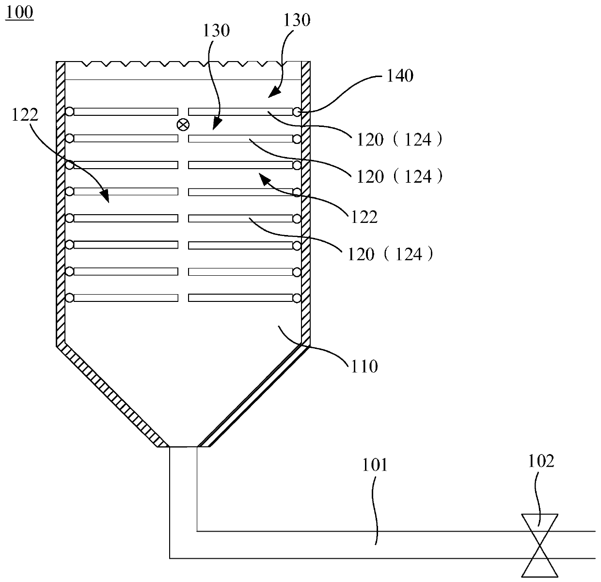
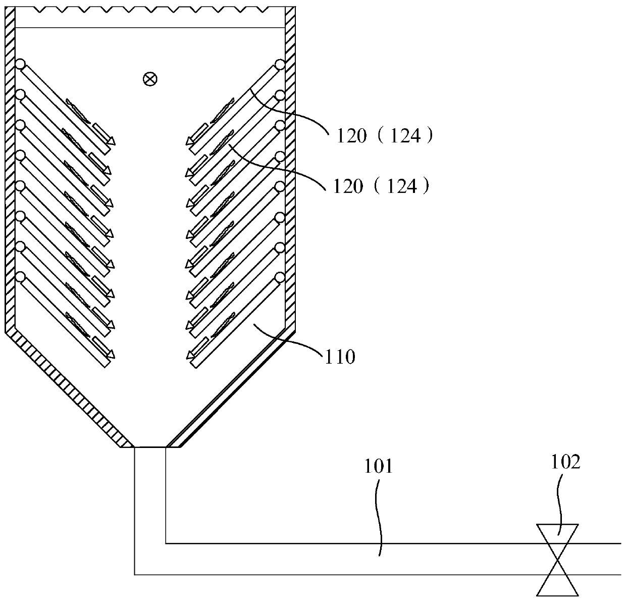
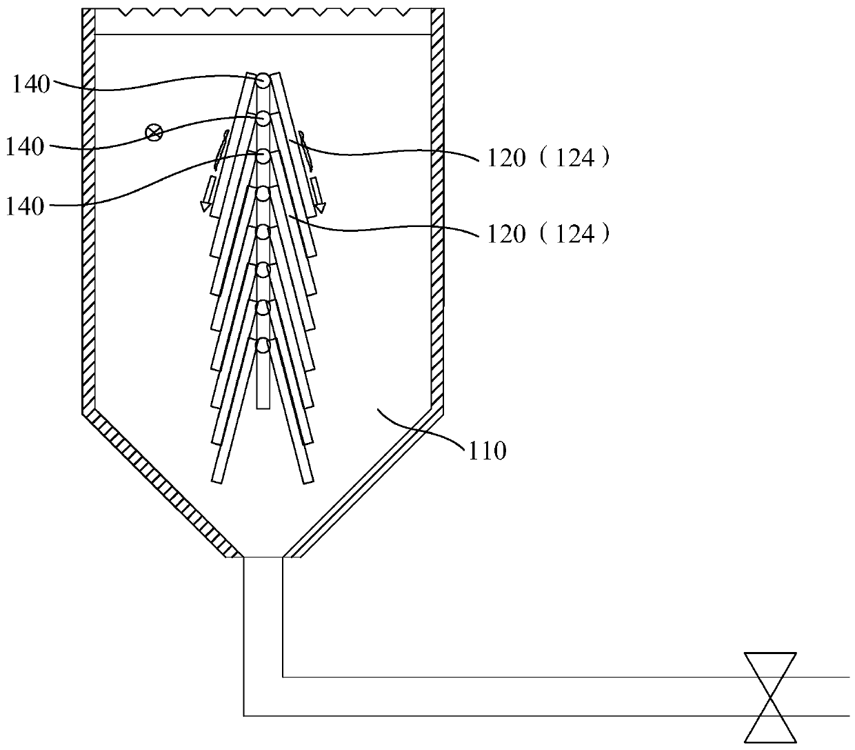
The invention relates to a sludge discharging method of a sedimentation tank. The sludge discharging method comprises the following steps that a sedimentation tank is provided, the sedimentation tankcomprises a tank body used for containing sewage, a plurality of sedimentation pieces and a sludge discharging pipe, the sedimentation pieces are arranged in the tank body in the depth direction of the tank body and are used for dividing the inner space of the tank body into a plurality of water passing spaces, and the sedimentation pieces can rotate between a first position and a second position;when the sedimentation pieces are positioned at the first position, the inclination angle of the sedimentation pieces relative to the tank body is marked as a first angle, so that mud in sewage willprecipitate onto the sedimentation pieces when the sewage flows through the water passing spaces; when the sedimentation pieces are located at the second position, the inclination angle of the sedimentation pieces relative to the tank body is marked as a second angle, so that the deposited mud is separated from the sedimentation pieces by virtue of gravity and falls into the bottom of the tank body; the sludge discharging pipe is arranged at the bottom of the tank body; and after the sedimentation pieces rotate to the second position, the deposited mud settled to the bottom of the tank body and sewage water body are discharged out of the tank body through the sludge discharging pipe at regular intervals by means of negative pressure at the same time.

Description

Technical field [0001] The invention relates to the technical field of environmental protection, in particular to a sludge discharge method for a sedimentation tank. Background technique [0002] Timely sludge discharge from the sedimentation tank is an extremely important task in the operation and management of the sedimentation tank. If the sludge is not discharged in time, anaerobic fermentation will occur, which will cause the sludge to float, which not only destroys the normal operation of the sedimentation tank, but also makes the water quality of the sedimentation tank. deterioration. Summary of the invention [0003] Based on this, it is necessary to provide a sludge discharge method for the sedimentation tank with simple operation and low energy consumption. [0004] A method for discharging sludge in a sedimentation tank includes the following steps: [0005] A sedimentation tank is provided. The sedimentation tank includes a tank body for accommodating sewage, a plurality...

Claims


Application Information

Patent Timeline
Patent Type & Authority Applications(China)
IPC IPC(8): B01D21/00B01D21/02B01D21/24B01D21/28
CPCB01D21/0045B01D21/02B01D21/28B01D21/245
Inventor 李继张小磊徐志亮冯健沛焦恒恒
Owner SHENZHEN UNIVERSILICON ENVIRONMENTAL SCI & TECH CO LTD
Why Eureka
Try Eureka