Positioning and grooving mechanism for pipe pile end square plate

A technology for pipe piles and slab grooves, which is applied in the field of positioning and grooving mechanisms, can solve problems such as reducing engineering efficiency and increasing installation difficulty, and achieves the effects of reducing construction difficulty, increasing construction efficiency, and reducing grooving difficulty.

Active Publication Date: 2020-04-10
嘉兴晨坤金属制品有限公司
View PDF6 Cites 2 Cited by
  • Summary
  • Abstract
  • Description
  • Claims
  • Application Information

AI Technical Summary

Problems solved by technology

[0003] For the mechanical connection of square tubular ends, most of them need to weld a square plate at the end, and mechanically connect through the slots on the square plates at the ends of the two square tube piles. However, most of the existing slots are manually picked up. The material is formed by stamping, and it is difficult to ensure that the stamped slots are all in the same position, which increases the difficulty of installation and reduces the engineering efficiency

Method used


Image

  • Positioning and grooving mechanism for pipe pile end square plate
  • Positioning and grooving mechanism for pipe pile end square plate
  • Positioning and grooving mechanism for pipe pile end square plate

Examples


Embodiment 1

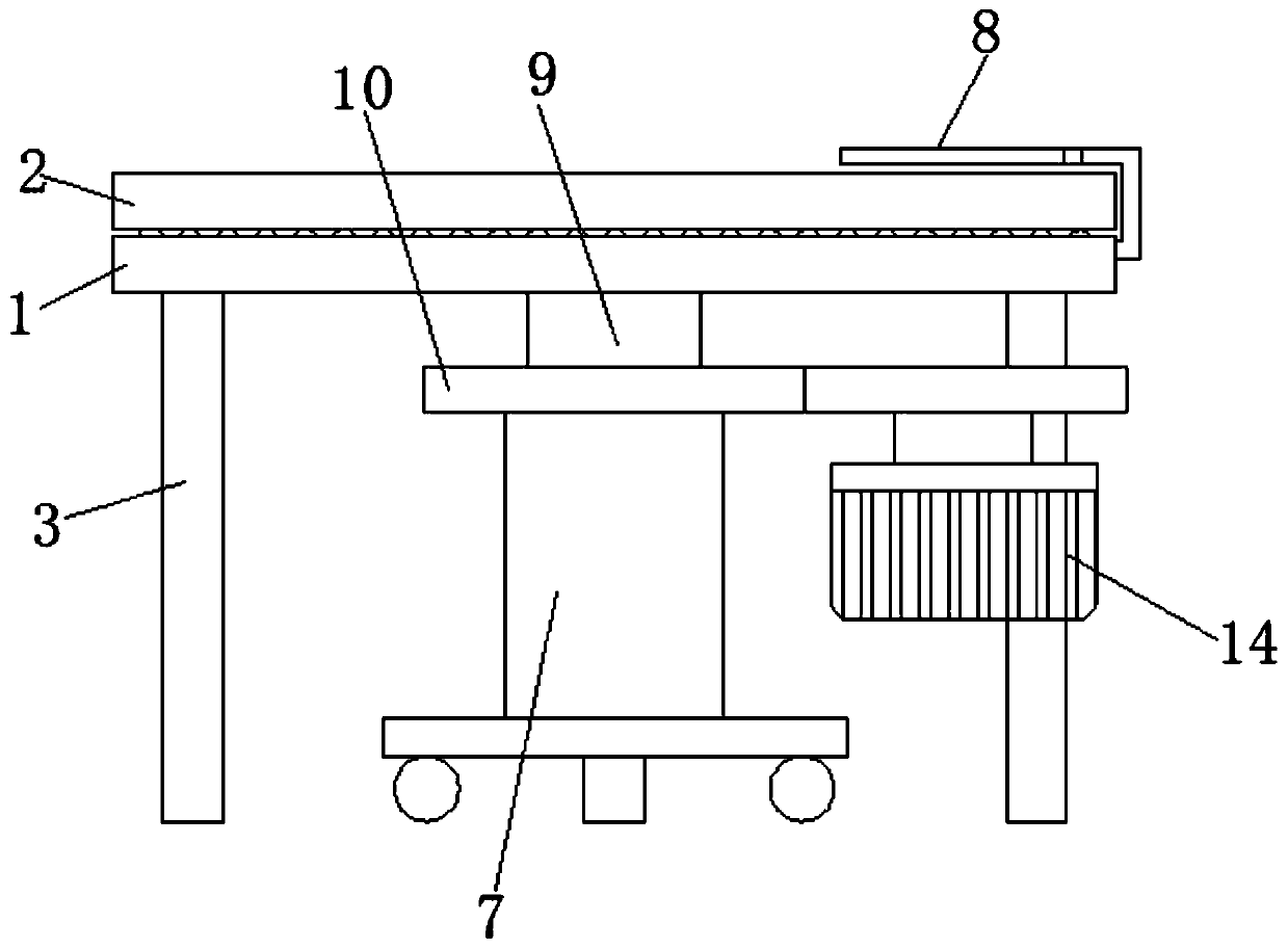
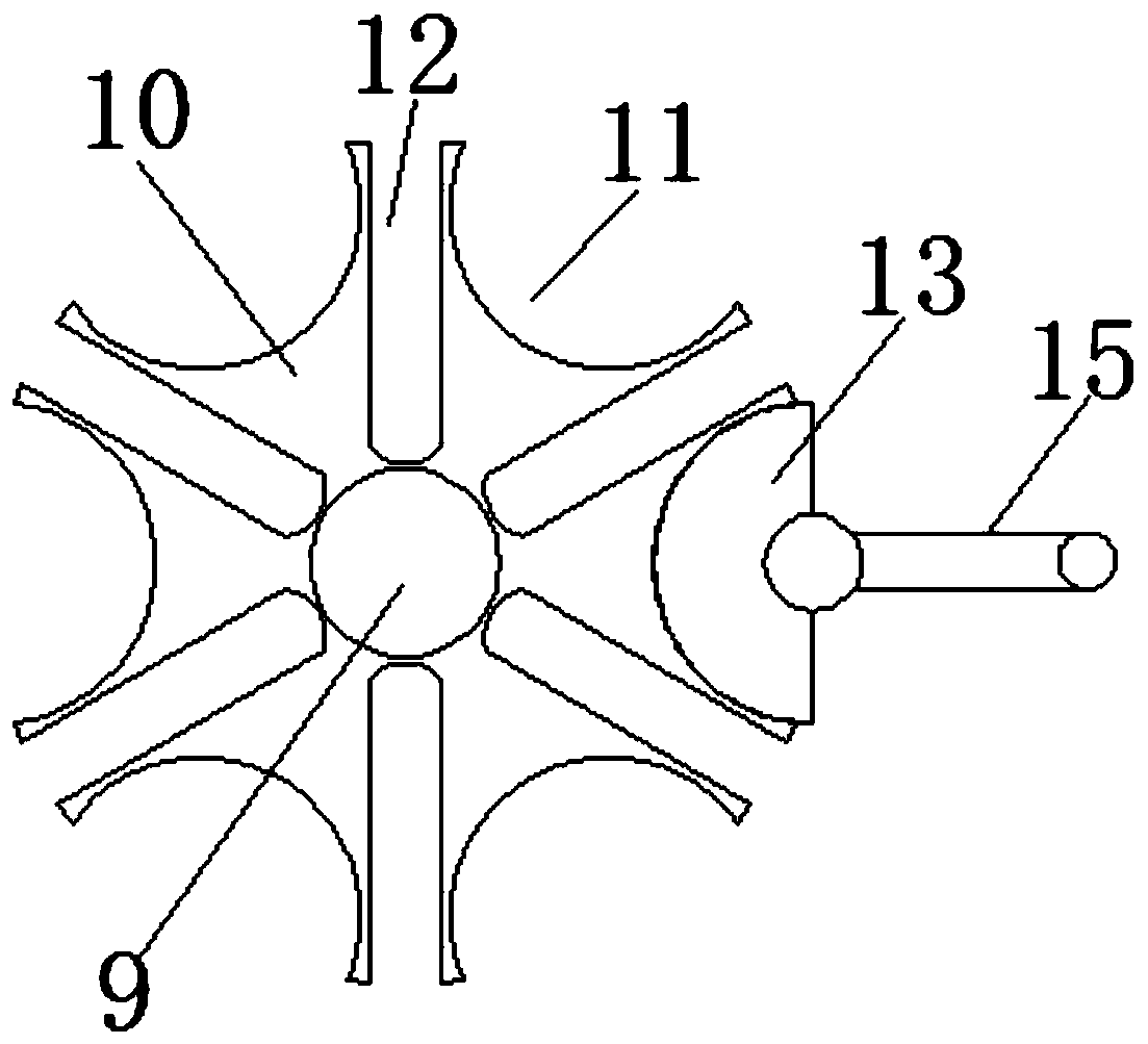
[0032] see Figure 1-7 , according to an embodiment of the present invention, a positioning and slotting mechanism for a square plate at the end of a pipe pile includes a bottom plate 1, a panel 2 is arranged on the bottom plate 1, and a plurality of support legs 3 are fixed under the bottom plate 1, Said panel 2 is evenly provided with square plate grooves 4, wherein one of the square plate grooves 4 is provided with a stamping machine 5, and one of the square plate grooves 4 is a blanking square plate groove, and the bottom of the blanking square plate groove is provided with a The bottom plate 1 is provided with a blanking through hole 6, a material receiving mechanism 7 is placed under the blanking through hole 6, and a blanking mechanism is arranged on the plurality of square plate grooves 4. One side of the blanking mechanism An interception mechanism 8 is provided, and a transmission rod 9 is fixed at the lower end of the middle part of the panel 2, and the transmission...

Embodiment 2

[0035] see Figure 1-7 , for the bottom plate 1, an annular groove 16 is opened on the bottom plate 1, and a plurality of rollers 17 are arranged in the annular groove 16, and a square plate 18 is placed on the roller 17.

[0036] As for the base plate 1 , a through hole is opened on the base plate 1 , and a bearing is embedded in the through hole, and the transmission rod 9 is connected with the base plate 1 through the bearing.

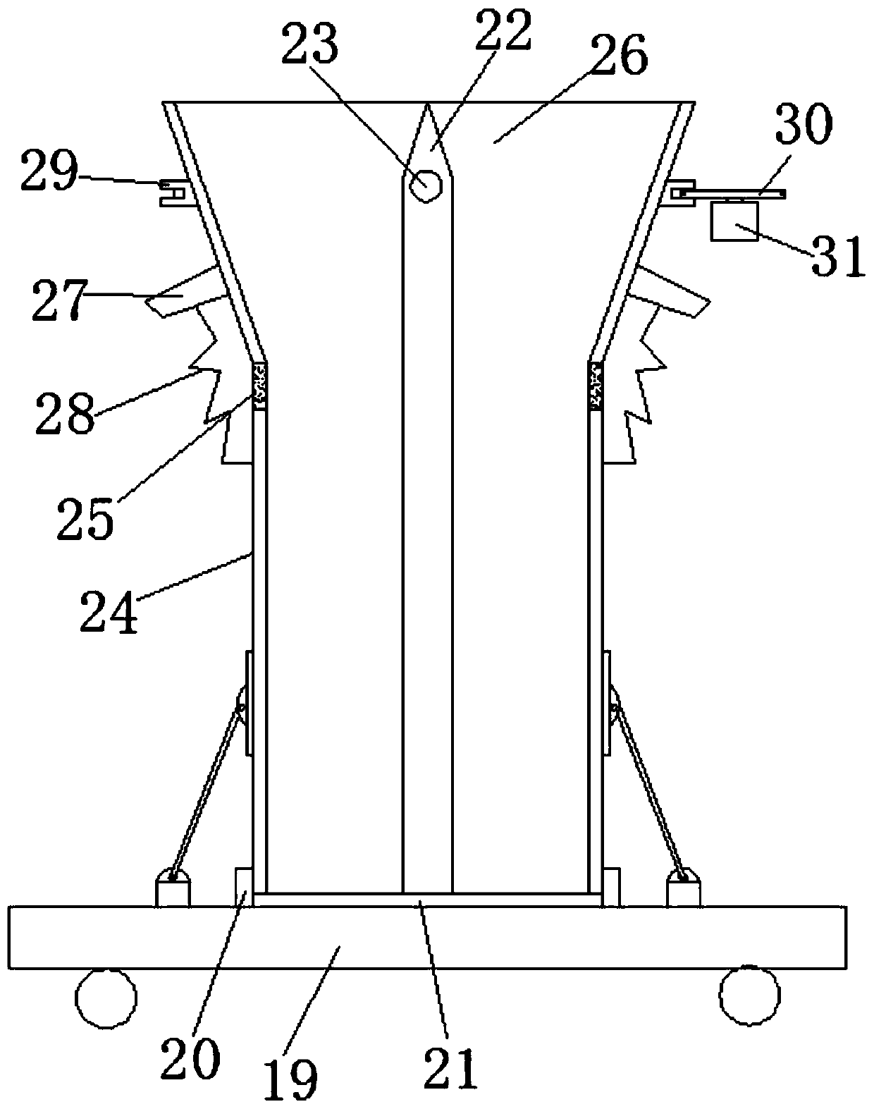
[0037] For the material receiving mechanism 7, the material receiving mechanism 7 includes a base 19, the base 19 is provided with a placement groove 20, the placement groove 20 is provided with a horizontal plate 21, and the horizontal plate 21 is fixedly provided with Insert rod 22.

[0038] For the insertion rod 22, a lifting hole 23 is provided on the insertion rod 22, and the side length of the horizontal plate 21 is longer than that of the square plate.

[0039] For the horizontal plate 21, a limit mechanism is placed on the horizontal plate...


PUM


Abstract

The invention discloses a positioning and grooving mechanism for a pipe pile end square plate. The mechanism comprises a bottom plate, wherein a face plate is arranged on the bottom plate, a pluralityof supporting legs are fixedly arranged below the bottom plate, square plate grooves are uniformly formed in the face plate, a punching machine is arranged on one of the square plate grooves, one ofthe square plate grooves is a discharging square plate groove, a discharging through hole formed in the bottom plate is formed below the discharging square plate groove, a material receiving mechanismis placed below the discharging through hole, a discharging mechanism is arranged on the plurality of square plate grooves, an intercepting mechanism is arranged on one side of the discharging mechanism, a transmission rod is fixedly arranged at the lower end of the middle of the face plate, the transmission rod movably penetrates through the bottom plate, a rotating disc is fixedly arranged at the end, far away from the face plate, of the transmission rod, and a plurality of static holes are uniformly formed in the rotating disc. The mechanism has the beneficial effects that rapid stamping is carried out, the grooving difficulty of manual stamping is relieved, and meanwhile, the grooving precision is increased, the situation that the construction is misaligned is reduced, and the construction efficiency is improved.

Description

technical field [0001] The invention relates to the field of connecting the ends of square pipe piles, in particular to a positioning and slotting mechanism for square plates at the ends of pipe piles. Background technique [0002] In the construction industry, since the length of a pile does not reach the depth specified in the design, it is necessary to connect the prefabricated piles one by one and continue to drive down until they reach the designed depth. During this process, the prefabricated piles need to be pile-connected, that is, the pile-connecting is a process of connecting the top of the previous pipe pile that has been driven in with the lower end of the latter pipe pile. [0003] For the mechanical connection of square tubular ends, most of them need to weld a square plate at the end, and mechanically connect through the slots on the square plates at the ends of the two square tube piles. However, most of the existing slots are manually picked up. The materia...

Claims


Application Information

Patent Timeline
Patent Type & Authority Applications(China)
IPC IPC(8): B21D17/02B21D43/00B21D43/20B21D43/22
CPCB21D17/02B21D43/003B21D43/20B21D43/22
Inventor 俞敏芳
Owner 嘉兴晨坤金属制品有限公司
Why Eureka
Try Eureka