Full-automatic laser coding line

A technology of laser coding and laser coding machine, which is applied in the direction of laser welding equipment, welding equipment, metal processing equipment, etc., can solve the problems of hidden safety hazards, low efficiency, high labor costs, etc., and achieve the effect of rapid diversion

Pending Publication Date: 2020-04-10
广东金亨制罐有限公司
View PDF0 Cites 2 Cited by
  • Summary
  • Abstract
  • Description
  • Claims
  • Application Information

AI Technical Summary

Problems solved by technology

This makes one worker need to take care of multiple processes, or requires multiple workers to cooperate with each other, resulting in high labor costs and low efficiency, and the edges and corners of the board are sharp and elastic, and manual operation poses safety hazards

Method used


Image

  • Full-automatic laser coding line
  • Full-automatic laser coding line
  • Full-automatic laser coding line

Examples


Embodiment Construction

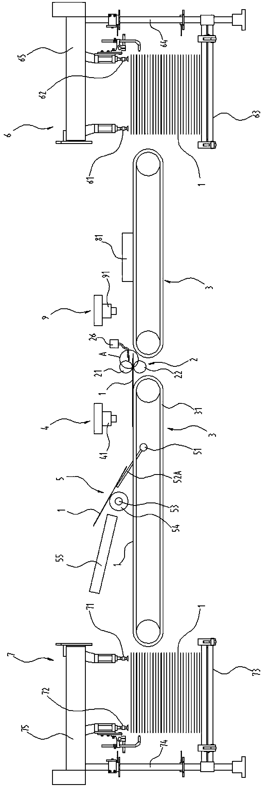
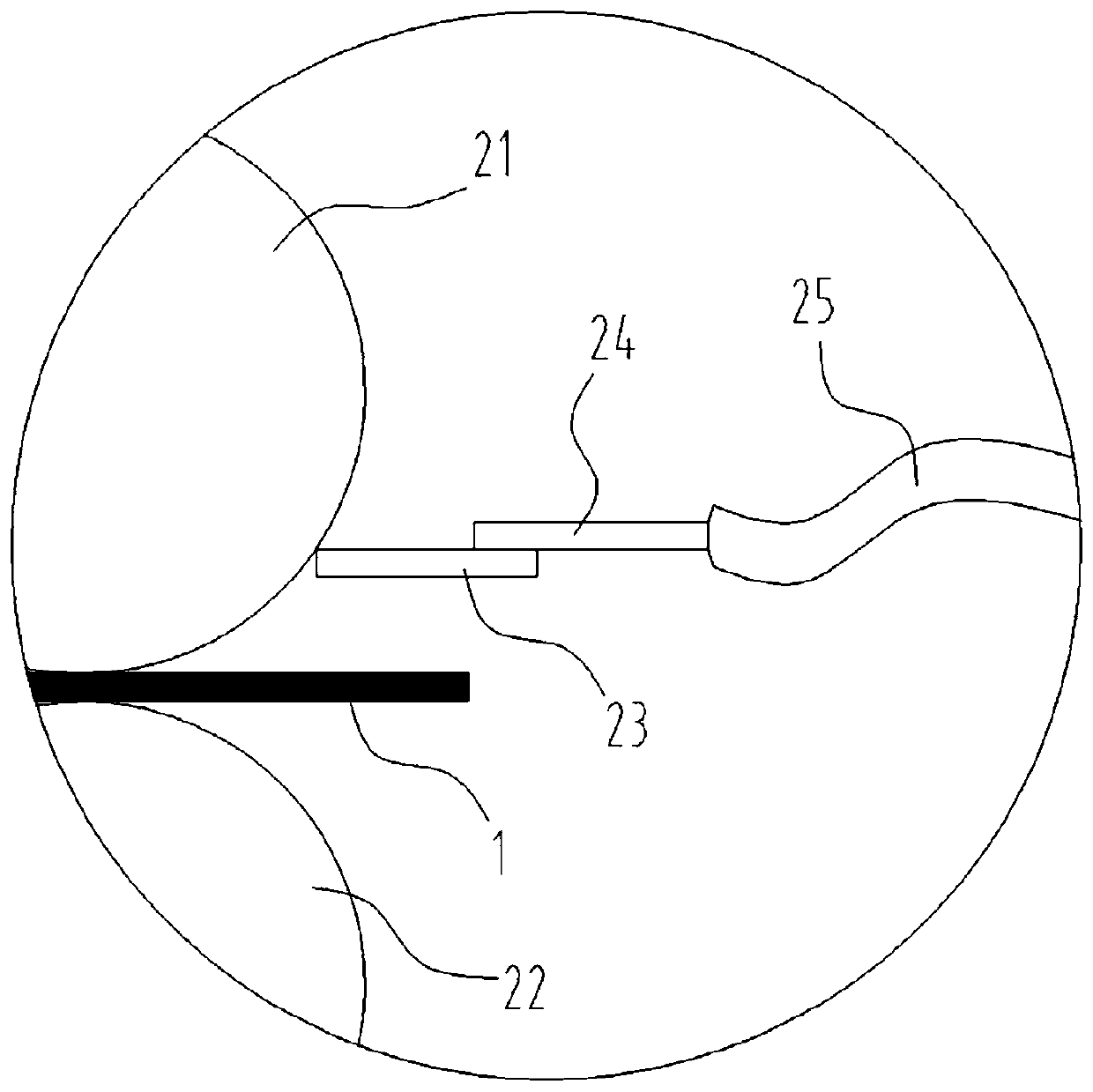
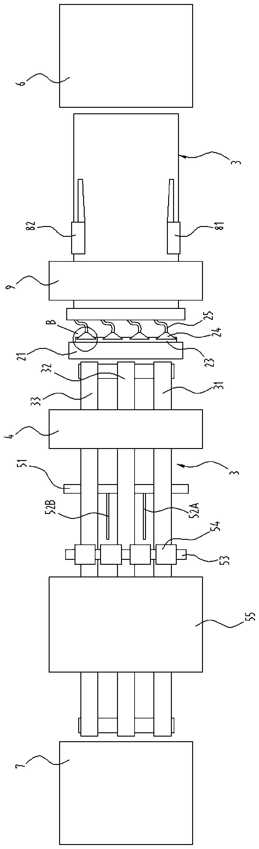
[0029] In order to make the purpose of the present invention, technical solutions and advantages clearer, the following will combine figure 1 - Figure 4 The accompanying drawings describe the present invention in further detail.

[0030] refer to figure 1 - Figure 4 As shown, a fully automatic laser coding line includes a conveyor belt 3, left and right gauges 81, 82, a laser coding machine 9, a detection device 4, and a pick-and-storage device 5.

[0031] The plate 1 is placed on the conveyor belt 3 for transmission through the left and right gauges 81, 82, the laser coding machine 9, the detection device 4, and the picking device 5.

[0032] The left and right side gauges 81, 82 are respectively arranged on the left and right sides of the feeding end of the conveyor belt 3, and the left and right side gauges 81, 82 are preferably common pneumatic side gauges on the market.

[0033] The laser coding machine 9 is arranged on the top of the conveyor belt 3, and is located...


PUM


Abstract

The invention discloses a full-automatic laser coding line. A plate is placed on a conveying belt for conveying; left and right side gauges are arranged at the left and right sides of the feeding endof the conveying belt respectively; a laser coding machine is arranged above the conveying belt and on the rear side of the left and right gauges, and a laser head of the laser coding machine faces the conveying belt; a detection device is arranged on the rear side of the laser coding machine, the detection device comprises a front detection camera arranged above the conveying belt, and the frontdetection camera faces the conveying belt; a defective product tray is arranged above the conveying belt and behind the detection device; and a guide rotating shaft links a guide supporting rod to swing and ascend when driven to rotate by a guide driving device, so that the plate on the conveying belt is guided by the guide supporting rod during conveying to enter the defective product ray. According to the full-automatic laser coding line, full-automatic alignment, coding, detection and screening are realized, and the efficiency is extremely high.

Description

technical field [0001] The invention relates to the field of coding equipment, in particular to a fully automatic laser coding line. Background technique [0002] Plates such as thin metal plates are widely used. When used to manufacture boxes, tanks and other containers, it is often necessary to laser-etch patterns, codes, etc. on the plate before forming. Most of the current laser coding machines are set up separately, so the boards are usually placed on the laser coding equipment manually for alignment and coding, and then manually removed for stacking. Before stacking, the patterns on the boards need to be inspected and screened In order to avoid the plate that failed to print into the forming process. This makes a worker need to take care of multiple processes, or requires multiple workers to cooperate with each other, resulting in high labor costs and low efficiency, and the edges and corners of the board are sharp and elastic, and there are potential safety hazards i...

Claims


Application Information

Patent Timeline
Patent Type & Authority Applications(China)
IPC IPC(8): B23K26/16B23K26/362B23K26/70
CPCB23K26/16B23K26/362B23K26/702
Inventor 吴浩生沈文堤
Owner 广东金亨制罐有限公司
Why Eureka
Try Eureka