Connecting box bus bar welding machine and welding detecting method thereof

A technology of bus bars and welding machines, applied in welding equipment, welding equipment, auxiliary welding equipment, etc., can solve the problems of low degree of automation, burnt out components, and can not work normally, so as to improve the degree of automation, ensure stability, welding accurate effect

Pending Publication Date: 2017-09-08
KUNSHAN MENGTEZHAN PRECISION ELECTROMECHANICAL CO LTD
View PDF13 Cites 6 Cited by
  • Summary
  • Abstract
  • Description
  • Claims
  • Application Information

AI Technical Summary

Problems solved by technology

If the junction box is damaged or the connection is not reliable, the junction box will not work properly, so when the solar module is partially covered, the entire solar module system will not work normally, and the covered part will emit a lot of heat, which will burn the module seriously
At present, the existing junction boxes for solar cell modules are all welded manually, the production efficiency is low, and the welding quality cannot be guaranteed. Later, some welding equipment gradually became available, but the following problems still exist, such as the invention patent with the patent number 201410173366.9 , the disclosed junction box automatic welding machine, the position of its welding components is uncontrollable, still needs manual adjustment, its degree of automation is low, and in the existing equipment, when welding, due to the complicated structure of welding wire transmission, the equipment is large in size, and The welding head of the traditional equipment is directly welded. Due to the unevenness of the product surface, some welding heads are not pressed against the welding wire. In the end, there is no welding liquid coating, resulting in incomplete welding and other problems, and the product cannot be detected at any time after welding. welding quality

Method used


Image

  • Connecting box bus bar welding machine and welding detecting method thereof
  • Connecting box bus bar welding machine and welding detecting method thereof
  • Connecting box bus bar welding machine and welding detecting method thereof

Examples


Embodiment 1

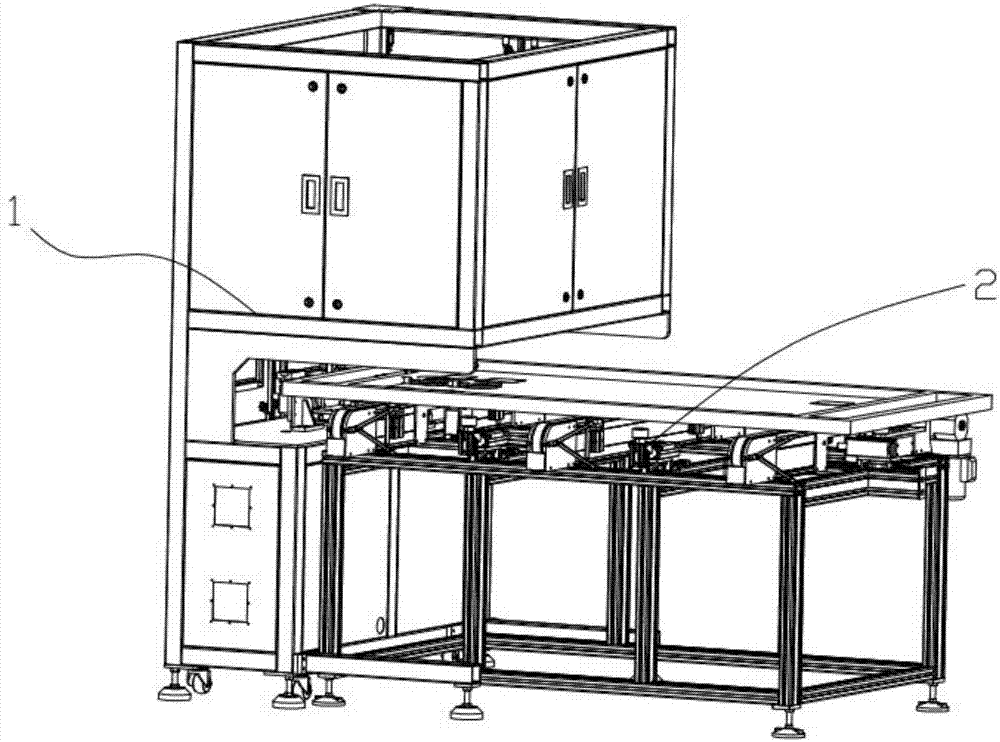
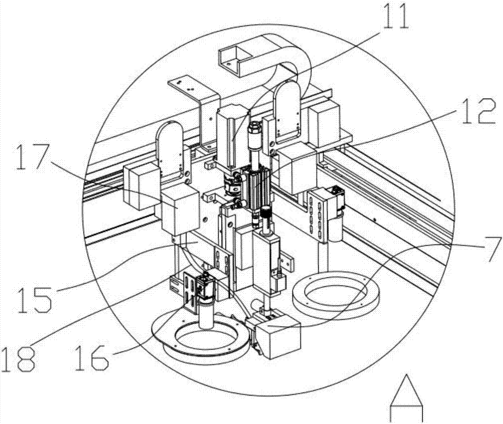
[0026] Such as figure 1 , figure 2 , image 3 As shown, the present invention proposes a junction box bus bar welding machine, including a welding part 1, a loading part 3 and a transmission mechanism 2, the welding part 1 is located on the upper part of the loading part 3, and the transmission mechanism 2 is located on the On the side of the loading part 3, the loading part 3 includes a bottom plate 21, a slide rail 20 is arranged on the bottom plate 21, a slide plate is engaged on the slide rail 20, and a pulling cylinder 22 is connected to the slide plate , the upper part of the pulling cylinder 22 is connected with a guide plate 23, the two sides of the guide plate 23 are provided with guide wheels 24, and the guide plate 23 is perpendicular to the direction of the slide rail 20; the output end of the pulling cylinder 22 is connected with Jacking cylinder 25, the output end of described jacking cylinder 25 is connected with top plate 26, as Figure 5 As shown, the mate...

Embodiment 2

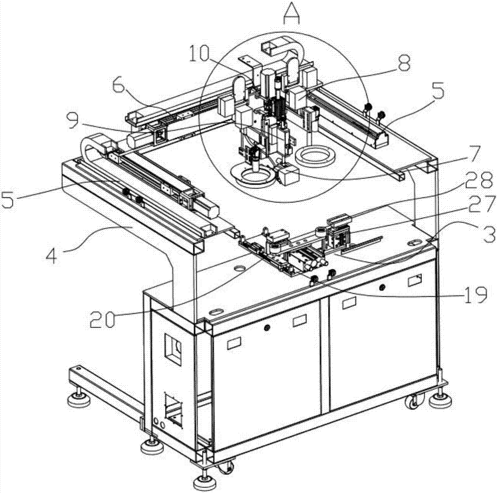
[0032]In order to ensure the cleanliness of the welding head, after using for a certain period of time, it can automatically move to the upper part of the welding head grinding device for automatic grinding, and remove the solder on the surface. The side of the loading part 3 is equipped with a welding head grinding device. The welding head grinding device includes a bearing cylinder 27, on which a grinding block 28 is arranged, and the temperature-controlled welding head 7 is transported to the grinding block 28 by a horizontal and vertical conveying mechanism to move back and forth for grinding.

Embodiment 3

[0034] Such as Figure 7 As shown, due to the heavy weight and large volume of solar energy, the transmission mechanism 2 includes a frame 29 on which several conveyor belts 31 are arranged, and the ends of the conveyor belts 31 are connected with a conveyor motor 30 A horizontal cylinder 32 is arranged between the conveyor belts 31, the output end of the horizontal cylinder 32 is connected with a positioning cylinder 33, the conveyor motor 30 controls the transmission of the conveyor belt 31, and the solar panel moves along the conveyor belt 31 to the welding part 1, the lower part The positioning cylinder 33 stretches upwards and has a supporting effect on the solar panel.

[0035] After the product welded by the above-mentioned embodiment is welded by the welding head welder, after the CCD camera obtains the surface image of the junction box, detect the black spots on both sides of the welding point, if the area of ​​the black spots is less than or equal to 10% of the overa...


PUM


Abstract

The invention provides a connecting box bus bar welding machine and a welding detecting method thereof. The connecting box bus bar welding machine comprises a welding part, a loading part and a conveying mechanism, the welding part is located at the upper portion of the loading part, and the conveying mechanism is located on the side edge of the loading part; the welding part comprises a support, and a horizontal-vertical conveying mechanism is arranged on the support and is provided with a welding mechanism; by means of the welding machine, three-axis positioning is matched with a CCD camera, automatic alignment is achieved, and the automatic degree is improved; in addition, the connecting box bus bar welding machine is more accurate in alignment compared with a traditional machine, a temperature sensor and a pressure sensor are arranged on a welding head, tight contact between the welding head and a welding wire is guaranteed by downwards pressing the welding head, welding is accurate, automatic lifting is carried out after corresponding temperature and pressure values are obtained, and the welding stability is guaranteed.

Description

technical field [0001] The invention relates to the field of automation equipment, in particular to a junction box bus bar welding machine and a welding detection method thereof. Background technique [0002] Photovoltaic modules are products that are connected and packaged by multiple photovoltaic cells. The photovoltaic module junction box is the key connection device for the solar module system. The function of the junction box is to prevent the hot spot effect when the solar module is partially blocked. If the junction box is damaged or the connection is not reliable, the junction box will not work properly, so when the solar module is partially covered, the entire solar module system will not work normally, and the covered part will emit a lot of heat, which will burn the module seriously . At present, the existing junction boxes for solar cell modules are all welded manually, the production efficiency is low, and the welding quality cannot be guaranteed. Later, some w...

Claims


Application Information

Patent Timeline
Patent Type & Authority Applications(China)
IPC IPC(8): B23K37/00B23K31/12
CPCB23K31/125B23K37/00B23K2101/36
Inventor 李剑峰
Owner KUNSHAN MENGTEZHAN PRECISION ELECTROMECHANICAL CO LTD
Why Eureka
Try Eureka