Automatic alignment type auxiliary mounting frame for mounting vehicle roller shaft

An automatic alignment and roller shaft technology, applied in metal processing, metal processing equipment, manufacturing tools, etc., can solve the problems of loss of physical strength, low accuracy of vehicle roller shafts, and reduce the intuitiveness of vehicle roller shaft alignment, etc., to improve The effect of stability and good precision

Active Publication Date: 2021-03-16
河南工学院
View PDF15 Cites 5 Cited by
  • Summary
  • Abstract
  • Description
  • Claims
  • Application Information

AI Technical Summary

Problems solved by technology

[0004] In the prior art, due to the heavy weight of the roller shaft of a large vehicle, the vehicle roller shaft is generally supported by a simple mounting frame during installation, but the existing mounting frame still has the following deficiencies in the actual process, such as: When the existing installation frame assists in the installation of the vehicle roller shaft, manual alignment is still required, so that the accuracy of the alignment of the vehicle roller shaft is low, and a lot of physical strength will be consumed during the manual alignment process, thereby reducing the The convenience of installing the vehicle roller shaft, and because the bottom of the existing mounting frame lacks an effective support structure, it is difficult to ensure the stability of the mounting frame when it is used only through the brake device on the universal wheel, and the existing mounting frame Due to the lack of an effective auxiliary structure, when the alignment is required, the alignment parts are only observed with the naked eye, thereby reducing the intuitiveness of the alignment of the vehicle roller shaft, and greatly reducing the installation efficiency of the vehicle roller shaft

Method used


Image

  • Automatic alignment type auxiliary mounting frame for mounting vehicle roller shaft
  • Automatic alignment type auxiliary mounting frame for mounting vehicle roller shaft
  • Automatic alignment type auxiliary mounting frame for mounting vehicle roller shaft

Examples


Embodiment 1

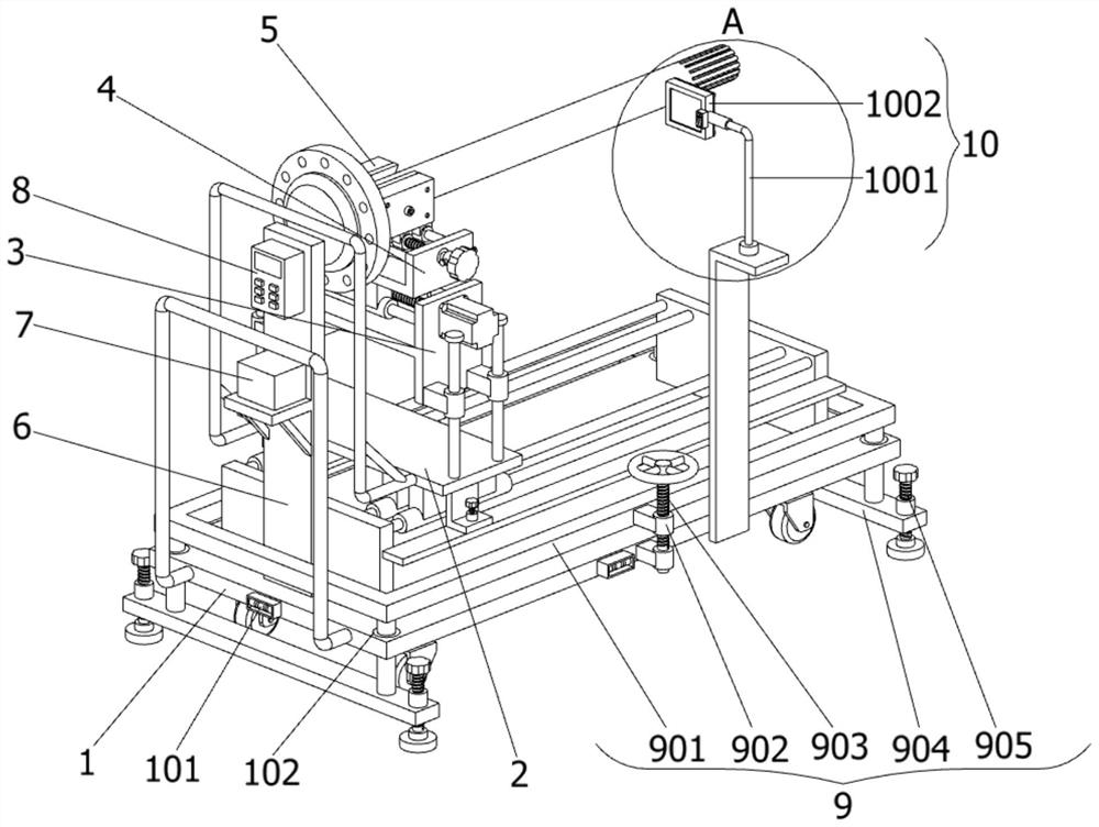
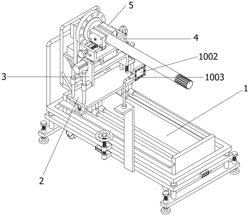
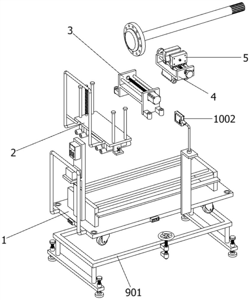
[0037] as attached figure 1 to attach Figure 10 As shown, the automatic alignment auxiliary mounting frame for the installation of the vehicle roller shaft in the preferred embodiment of the present invention includes: a bottom plate 1, the upper part of the bottom plate 1 is slidably connected with a sliding mechanism 2, the bottom plate 1 includes a vial 101 and a bushing 102, and the sliding The upper part of the mechanism 2 is provided with a height adjusting member 3 . The height adjustment member 3 includes an I-shaped lifting plate 301, a first sliding sleeve 302, an elevating motor 303 and a lifting screw 304, and the lower part of the left and right ends of the I-shaped lifting plate 301 is provided with two first sliding sleeves 302, and each first The inside of the sliding sleeve 302 is slidably connected with a limit sliding column fixed on the upper end surface of the sliding table 201 . Lifting motor 303 is installed on the left side of the bottom end surface ...

Embodiment 2

[0039] In a preferred embodiment, the auxiliary mechanism 10 includes a metal shaping hose 1001 , a magnifying glass 1002 , an LED light strip 1003 and a control switch 1004 . The metal shaping hose 1001 is fixedly connected to the top of the L-shaped support plate on the right side of the bottom plate 1, and the other end of the metal shaping hose 1001 is connected to a magnifying glass 1002, which is a square structure.

[0040] Further, an LED light strip 1003 is provided at the edge of the rear end of the magnifying glass 1002, and a control switch 1004 is installed on the right side of the front end of the magnifying glass 1002. The illumination effect of the magnifying glass cooperates with the magnifying effect of the magnifying glass 1002, thereby improving the intuition when the vehicle roller shaft is aligned.

Embodiment 3

[0042] In a preferred embodiment, two anti-slip parts 11 are arranged symmetrically inside the clamping mechanism 5 , and the anti-slip parts 11 include rubber anti-slip pads 1101 , limit posts 1102 , injection tubes 1103 and white powder 1104 . The middle part on the left side of the rubber anti-slip mat 1101 is connected with an injection pipe 1103, and the four corners on the left side of the rubber anti-slip mat 1101 are provided with a limit post 1102, and the interior of the injection pipe 1103 is connected with a sealing bolt through a thread, and the interior of the rubber anti-slip mat 1101 Filled with white powder 1104, by filling the inside of the rubber anti-slip mat 1101 with white powder 1104, when the rubber anti-slip mat 1101 is severely worn, the white powder 1104 will leak out from the inside of the rubber anti-slip mat 1101, so that the staff can find the rubber anti-slip in time The severe wear of the pad 1101 improves the reliability of the anti-skid member...


PUM


Abstract

The invention discloses an automatic alignment type auxiliary mounting frame for mounting a vehicle roller shaft. The mounting frame comprises a bottom plate, wherein a sliding mechanism is slidably connected to the upper portion of the bottom plate, and a height adjusting piece is arranged on the upper portion of the sliding mechanism; a left-right adjusting piece is arranged on the upper portionof the height adjusting piece, and a clamping mechanism is arranged at the upper portion of the left-right adjusting piece; the roller shaft is clamped on the clamping mechanism; a mounting plate isfixedly connected to the front side of the upper end surface of the bottom plate, and a storage battery and a controller are arranged at the upper portion of the front end surface of the mounting plate; a supporting mechanism is arranged at the bottom of the bottom plate, and the rear side of the right end face of the bottom plate is connected with an auxiliary mechanism through an L-shaped supporting plate; two anti-skid pieces are symmetrically arranged on the inner side of the clamping mechanism; and the sliding mechanism comprises a sliding table, four first sliding cylinders and an L-shaped brake plate, the four first sliding cylinders are fixedly connected to the bottom of the sliding table in a bilateral symmetry mode, a limiting guide rod is slidably connected to the interior of each first sliding cylinder, and a strip-shaped plate is welded between the right end faces of the two fixing plates, and the L-shaped brake plate in contact with the upper end face of the strip-shapedplate is arranged on the right side of the bottom end face of the sliding table.

Description

technical field [0001] The invention relates to the technical field of mounting frames, and more specifically relates to an automatic alignment auxiliary mounting frame for installing a vehicle roller shaft. Background technique [0002] The vehicle roller shaft, also called the drive shaft, is the shaft that connects the differential to the drive wheels. The half shaft is the shaft that transmits torque between the gearbox reducer and the drive wheel. There is a universal joint at the inner and outer ends of the drive wheel, respectively connected to the reducer gear and the inner ring of the hub bearing through the splines on the universal joint. [0003] Patent CN201811351683.X discloses an auxiliary bracket for installing a camshaft on an axle, including a support assembly and a positioning assembly; the fixing assembly includes a base, two positioning grooves, a fixing hook, and a driving member, and the axle is placed in the two positioning grooves , the fixed hook is...

Claims


Application Information

Patent Timeline
Patent Type & Authority Applications(China)
IPC IPC(8): B23P19/00B23P19/10
CPCB23P19/00B23P19/10
Inventor 温永美李坤王国盛睢利铭李倩冯铭祥
Owner 河南工学院
Why Eureka
Try Eureka