
Laser marking machine

A technology of laser marking machine and laser marking head, which is applied in laser welding equipment, welding equipment, metal processing equipment, etc., and can solve the problems of low marking accuracy and low marking efficiency

Pending Publication Date: 2020-04-10
浙江云景精密设备有限公司
View PDF0 Cites 6 Cited by
  • Summary
  • Abstract
  • Description
  • Claims
  • Application Information

AI Technical Summary

Problems solved by technology

[0002] Existing laser marking machine, it comprises frame, is provided with conveyer belt on the frame, is also provided with laser marking head on the frame above conveyer belt, during work, the workpiece to be marked is placed on conveyer belt However, this kind of laser marking machine, firstly, the workpiece to be marked is not well positioned during marking, and the marking accuracy is low; secondly, its marking Low efficiency. After marking a workpiece, it needs to wait for the next workpiece to enter, and the marking efficiency is low

Method used


Image

  • Laser marking machine
  • Laser marking machine
  • Laser marking machine

Examples


Embodiment Construction

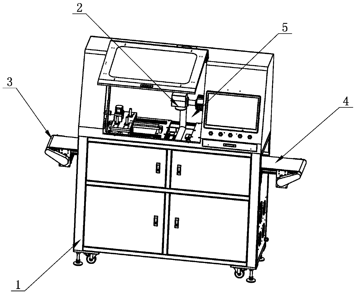
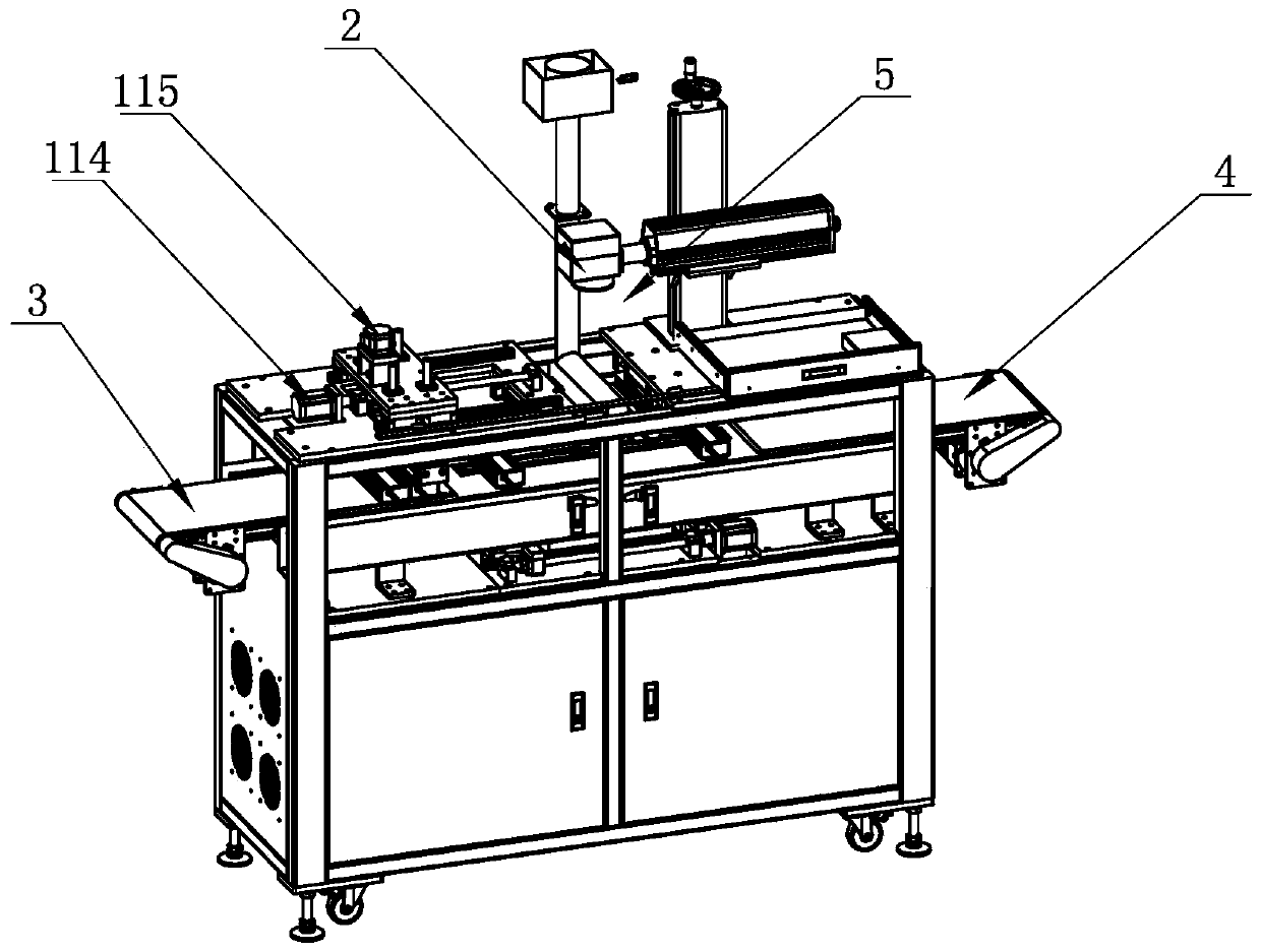
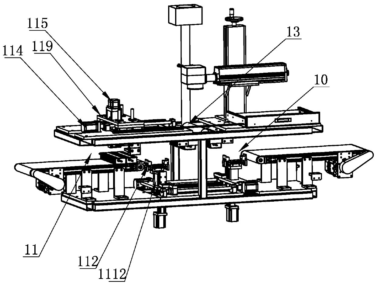
[0024] Such as Figure 1-6 As shown, a laser marking machine includes a frame 1 and a laser marking head 2. The frame 1 is provided with an input conveyor belt 3 and an output conveyor belt 4 along the horizontal direction. The input conveyor belt 3 is located at the rear side of the output conveyor belt 4 and Set at intervals, a marking station 5 is provided between the input conveyor belt 3 and the output conveyor belt 4, and the marking station 5 is provided with a first clamp 6 and a second clamp 7 for clamping the workpiece to be marked and for controlling the first The first control part 8 for clamping or loosening the clamp 6, the second control part 9 for controlling the clamping or loosening of the second clamp 7, the laser marking head 2 is located above the first clamp 6 and the second clamp 7 , the first fixture 6 and the second fixture 7 are respectively located on both sides of the laser marking head 2 along the horizontal direction, and also includes a tool for ...


PUM


Abstract

The invention relates to a laser marking machine. The laser marking machine comprises a rack, a laser marking head, an inputting conveyor belt and an outputting conveyor belt, wherein a marking station is provided with a first clamp and a second clamp which are used for clamping to-be-marked workpieces, a first control piece used for controlling the first clamp to conduct clamping or loosening anda second control piece used for controlling a second control piece to conduct clamping or loosening, the laser marking head is located above the first clamp and the second clamp, and the first clampand the second clamp are located at the two sides of the laser marking head in the horizontal direction respectively. The laser marking machine furthermore comprises a discharging assembly which is used for alternately delivering the workpieces on the first clamp and the second clamp onto the outputting conveyor belt one by one after marking is finished and a feeding assembly which is used for alternately feeding the to-be-marked workpieces on the inputting conveyor belt into the first clamp and the second clamp one by one. According to the technical scheme, the laser marking machine has the advantages of being high in marking precision and efficiency and capable of greatly lowering the cost.

Description

technical field [0001] The invention relates to a laser marking machine. Background technique [0002] Existing laser marking machine, it comprises frame, is provided with conveyer belt on the frame, is also provided with laser marking head on the frame above conveyer belt, during work, the workpiece to be marked is placed on conveyer belt However, this kind of laser marking machine, firstly, the workpiece to be marked is not well positioned during marking, and the marking accuracy is low; secondly, its marking The efficiency is low. After a workpiece is marked, it needs to wait for the next workpiece to enter, and the marking efficiency is low. Contents of the invention [0003] Purpose of the present invention: In order to overcome the defects of the prior art, the present invention provides a laser marking machine, which has high marking precision and high efficiency, and greatly reduces the cost. [0004] The technical scheme of the present invention: a laser marking...

Claims


Application Information

Patent Timeline
Patent Type & Authority Applications(China)
IPC IPC(8): B23K26/362B23K26/142B23K26/70
CPCB23K26/362B23K26/142B23K26/702
Inventor 徐佐平
Owner 浙江云景精密设备有限公司
Learn More