
Automatic centering and clamping machining tool for rotary workpiece

An automatic centering and workpiece technology, applied in the direction of metal processing, metal processing equipment, metal processing machinery parts, etc., can solve the problems of hidden safety hazards, high labor costs, low production efficiency, etc., and achieve low maintenance costs and high production efficiency , the effect of improving production efficiency

Pending Publication Date: 2020-04-10
TIANJIN UNIV
View PDF0 Cites 4 Cited by
  • Summary
  • Abstract
  • Description
  • Claims
  • Application Information

AI Technical Summary

Problems solved by technology

[0003] In the process of mechanical processing, manual operation is usually used for loading and unloading of large rotary workpieces. The production efficiency is low and the labor cost is too high.
[0004] For example, the processing of the inner and outer ring parts of the slewing ring is usually carried out by manual lifting, which is cumbersome to operate, with low production efficiency and potential safety hazards

Method used


Image

  • Automatic centering and clamping machining tool for rotary workpiece
  • Automatic centering and clamping machining tool for rotary workpiece
  • Automatic centering and clamping machining tool for rotary workpiece

Examples


Embodiment Construction

[0030] The present invention will be described in further detail below in conjunction with the accompanying drawings and specific embodiments. It should be understood that the specific embodiments described here are only used to explain the present invention, not to limit the present invention.

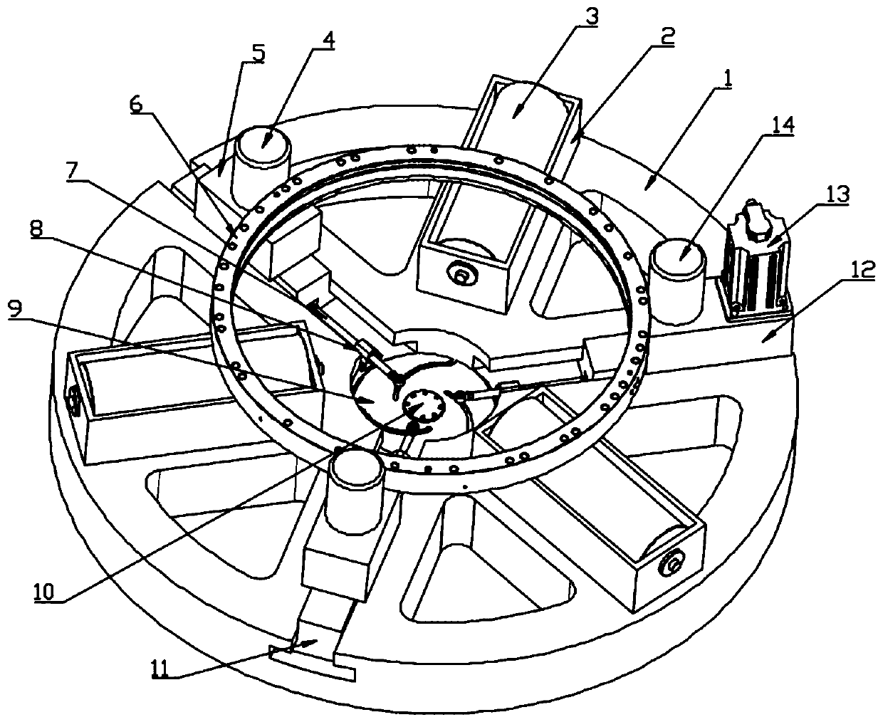
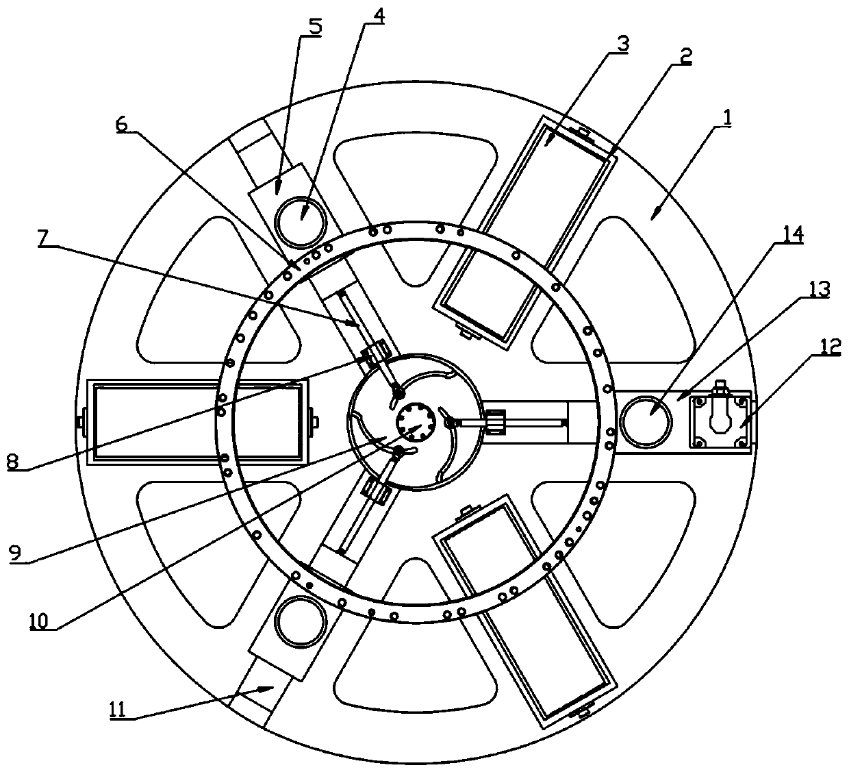
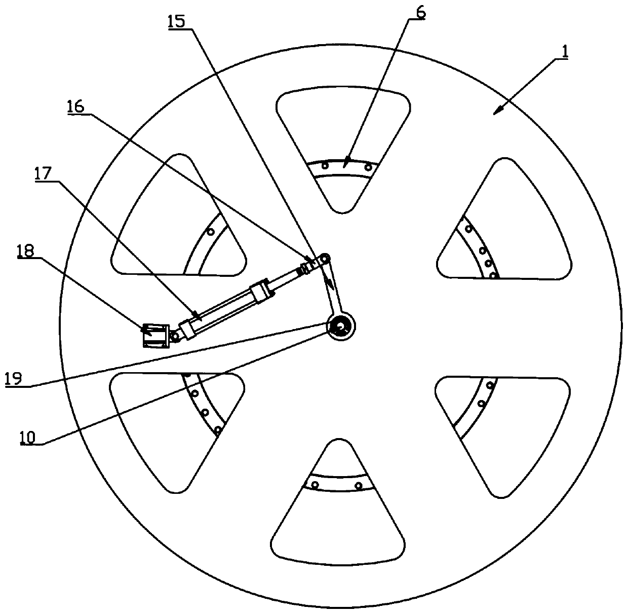
[0031] Such as Figure 1-Figure 5 As shown, an automatic centering and clamping processing tool for rotary workpieces includes a base 1, a power device, a part support driven device and a hydraulic clamping device. The power device includes a servo motor 13, a reducer 12, a power wheel 14, two driven wheels 4 and two connecting blocks 5, the part support driven device includes three support seats 2 and three support wheels 3, and the hydraulic clamping device includes Hydraulic driving device, cam linkage device and installation auxiliary device, hydraulic driving device includes hydraulic cylinder 17, mounting seat 18, connecting head 16, connecting rod 15 and connecting shaft 10, c...


PUM


Abstract

The invention discloses an automatic centering and clamping machining tool for a rotary workpiece. The automatic centering and clamping machining tool comprises a base, a servo motor, a speed reducer,a power wheel and driven wheels, at least two stages of stepped holes are formed in the center of the base, the stepped holes are used for installing a bearing, a connecting shaft is installed in thebearing, and the upper end of the connecting shaft is connected with a groove disc type cam; T-shaped grooves are formed in the upper end face of the base at equal intervals in the radial direction,positioning blocks are installed in the T-shaped grooves, the speed reducer is installed on one positioning block, connecting blocks are installed on the other positioning blocks, the driven wheels are installed on the connecting blocks, and the servo motor and the power wheel are installed on the speed reducer. Supporting seats are further arranged on the upper end face of the base at equal intervals in the radial direction, and supporting wheels are installed in the supporting seats in a rolling mode. The groove disc type cam is connected with the positioning blocks through columnar connecting rods and linear bearings; a hydraulic driving device is arranged on the lower end face of the base. The machining tool is simple in overall structure, low in cost, high in practicability and convenient to popularize.

Description

technical field [0001] The invention relates to the field of mechanical engineering, in particular to an automatic centering and clamping processing tool for rotary workpieces. Background technique [0002] Nowadays, the field of mechanical engineering is constantly promoting innovation around the goals of reducing operating costs, shortening production cycles, improving the production environment, and realizing intelligent manufacturing. [0003] In the process of mechanical processing, manual operation is usually used for loading and unloading of large rotary workpieces, which has low production efficiency and high labor costs. [0004] For example, the processing of the inner and outer ring parts of the slewing ring usually adopts the manual lifting method for loading and unloading, which is cumbersome to operate, with low production efficiency and potential safety hazards. Contents of the invention [0005] The purpose of the present invention is to overcome the defic...

Claims


Application Information

Patent Timeline
Patent Type & Authority Applications(China)
IPC IPC(8): B23Q3/08B23Q7/00
CPCB23Q3/082B23Q7/00
Inventor 王太勇马明珠孙熙冉张雷李勃邵文婷
Owner TIANJIN UNIV
Learn More