
Novel lifting type zero-sticking block structure

A lifting and sticking technology, applied in the field of zero sticking, can solve the problems of small size, easy loss, and increased manufacturing difficulty of the positioning device, and achieves the effect of low interchangeability and avoiding loss.

Inactive Publication Date: 2020-04-10
何君尧
View PDF0 Cites 0 Cited by
  • Summary
  • Abstract
  • Description
  • Claims
  • Application Information

AI Technical Summary

Problems solved by technology

[0003] In the prior art, detachable zero stickers are used for positioning. In actual use, due to the small size of the positioning device, it is easy to lose
Moreover, the structure and appearance of the positioning device are similar, and the assembly accuracy of the parts is generally within ±0.05mm. In order to avoid installation errors during use, the positioning device must have high interchangeability, which increases the difficulty of manufacturing.

Method used


Image

  • Novel lifting type zero-sticking block structure
  • Novel lifting type zero-sticking block structure
  • Novel lifting type zero-sticking block structure

Examples


Embodiment Construction

[0022] The technical solutions in the embodiments of the present invention will be clearly and completely described below with reference to the accompanying drawings in the embodiments of the present invention. Obviously, the described embodiments are only a part of the embodiments of the present invention, but not all of the embodiments.

[0023] In the description of the present invention, it should be understood that the terms "upper", "lower", "front", "rear", "left", "right", "top", "bottom", "inside", " The orientation or positional relationship indicated by "outside" is based on the orientation or positional relationship shown in the accompanying drawings, and is only for the convenience of describing the present invention and simplifying the description, rather than indicating or implying that the indicated device or element must have a specific orientation, so as to The specific orientation configuration and operation are therefore not to be construed as limitations of...


PUM


Abstract

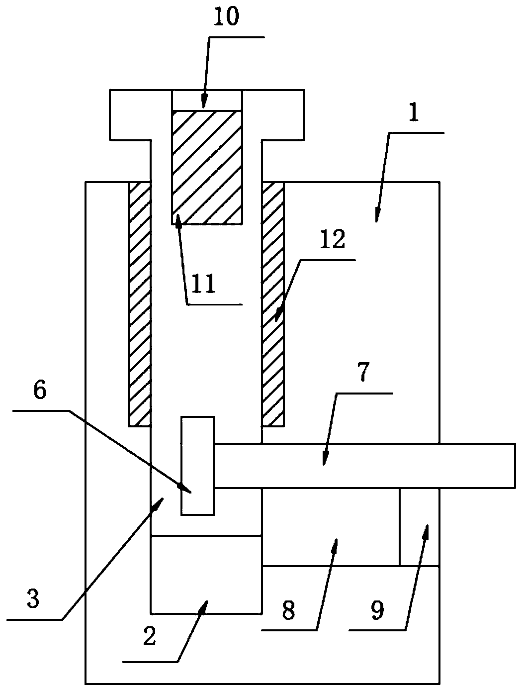
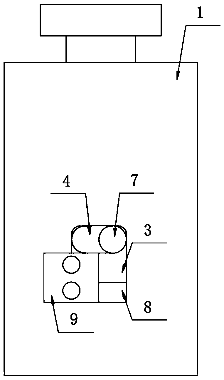
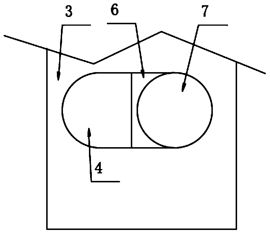
The invention discloses a novel lifting type zero-sticking block structure. The novel lifting type zero-sticking block structure comprises a zero sticking block installed on an inspection body, a mounting hole is formed in the inspection body, the zero sticking block is located on the mounting hole, a first sliding groove and a limiting cavity are formed in the mounting hole, the first sliding groove and the limiting cavity are in communication with each other, a mounting block is arranged in the limiting cavity, a limiting rod is fixedly mounted on the mounting block, an L-shaped sliding groove is formed in the inspection body, the L-shaped sliding groove and the mounting hole are in communication with each other, and one end of the limiting rod penetrates through the mounting block and the L-shaped sliding groove and extends to the outside of the inspection body, and a limiting block is fixedly installed on the inspection body. The structure has the advantages that the zero stickingblocks do not need to be disassembled, the loss is avoided, the zero sticking blocks do not need to be disassembled and assembled for many times, the machining precision can be guaranteed only when the parts are machined, and the requirement for interchangeability is not high.

Description

technical field [0001] The invention relates to the technical field of zero-sticking blocks, in particular to a novel lift-type zero-sticking block structure. Background technique [0002] In the assembly inspection tool, the inspection requirements of certain single products are often taken into account. Due to the different product parts, the position of the positioning point is also different. [0003] In the prior art, a detachable zero-sticking block is used for positioning, and in actual use, the positioning device is easily lost due to its small size. Moreover, the structure and appearance of the positioning device are similar, and the assembly accuracy of the parts is generally within ±0.05mm. In order to avoid installation errors during use, the positioning device must have high interchangeability, which increases the difficulty of manufacturing. SUMMARY OF THE INVENTION [0004] The purpose of the present invention is to propose a novel lift-type zero-sticking b...

Claims


Application Information

Patent Timeline
IPC IPC(8): B25B11/00
CPCB25B11/002
Inventor 何君尧
Owner 何君尧
Learn More