Magnetic shoe sintering electric kiln rotary line extension device and implementation method thereof

A magnetic tile sintering and extension device technology, applied in the direction of conveyor control devices, transportation and packaging, conveyor objects, etc., can solve problems such as difficulty in recruiting employees, achieve the effects of reducing labor intensity, low equipment cost, and reducing usage

Active Publication Date: 2020-04-10
HENGDIAN GRP DMEGC MAGNETICS CO LTD
View PDF14 Cites 0 Cited by
  • Summary
  • Abstract
  • Description
  • Claims
  • Application Information

AI Technical Summary

Problems solved by technology

It is very difficult to recruit employees for loading and unloading positions

Method used


Image

  • Magnetic shoe sintering electric kiln rotary line extension device and implementation method thereof
  • Magnetic shoe sintering electric kiln rotary line extension device and implementation method thereof
  • Magnetic shoe sintering electric kiln rotary line extension device and implementation method thereof

Examples


Embodiment

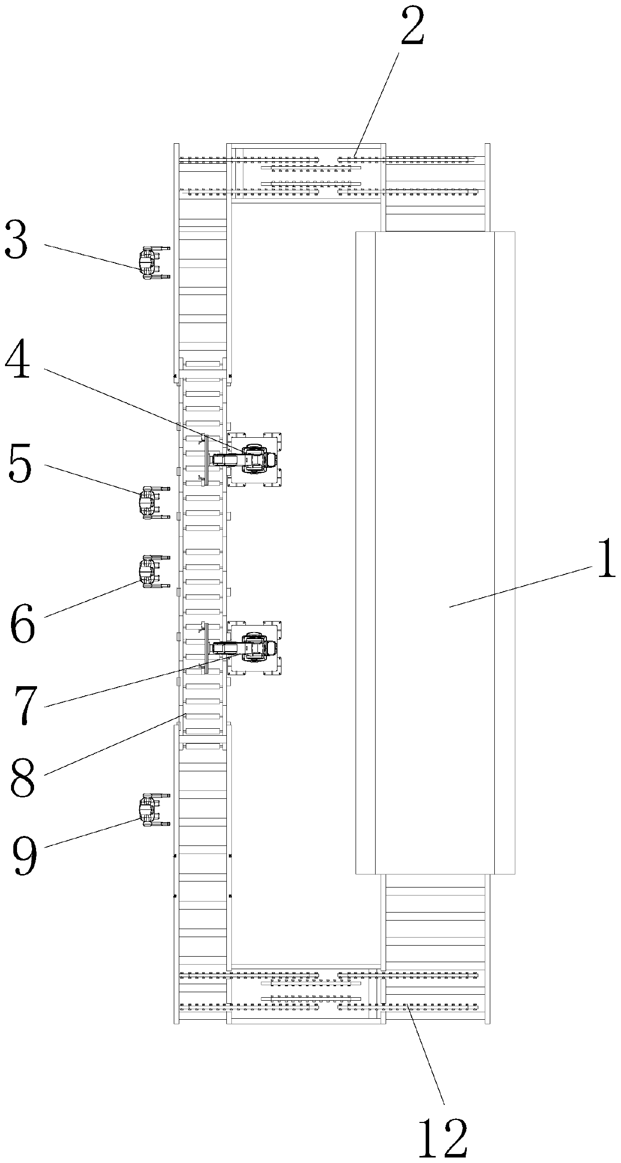
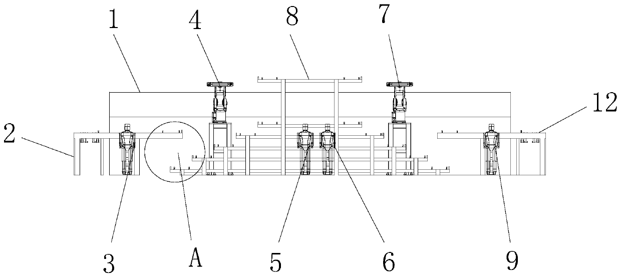
[0029] see Figure 1-4 , the present invention provides the following technical solutions: a magnetic tile sintering electric kiln rotating line extension device, including an electric kiln 1, the feeding end of the electric kiln 1 is provided with a feeding rotating line 12, and the feeding end of the electric kiln 1 is provided with a lower The feeding rotary line 2, the unloading rotary line 2 and the loading rotary line 12 are connected through the storage conveyor line 8, and the end of the blanking rotary line 2 close to the storage conveyor line 8 is provided with the first unloading station 3, and the feeding rotary The end of the line 12 close to the storage conveying line 8 is provided with a second loading station 9, and the side of the storage conveying line 8 far away from the electric kiln 1 is respectively provided with a second unloading station 5 and a first feeding station 6. A first robot 4 and a second robot 7 are respectively provided on the side of the co...

Embodiment 2

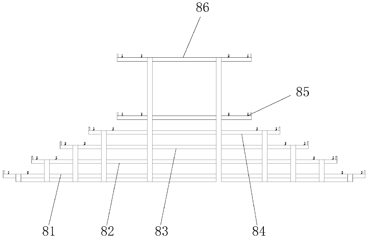
[0045] The difference between this embodiment and Embodiment 1 lies in: specifically, one more station is added to one side of the second unloading station 5 and the first loading station 6 respectively.

[0046] By adopting the above technical scheme, two workers are used to unload the magnetic tiles, and two workers are used to load the magnetic tiles, thereby reducing the labor intensity of the workers.

[0047] To sum up, the present invention can extend the rotary line by setting the storage conveying line, and carry out loading and unloading by robots, so as to realize the elimination of the workers who load the blanks of the late shift magnetic tiles and the unloaders who burn the finished magnetic tiles; The temperature of the working environment of the kiln is high. When the workers are working, the refrigeration facilities such as air conditioners and fans on the posts need to work. The workers in the present invention only need to work for eight hours, and the refrig...


PUM


Abstract

The invention discloses a magnetic shoe sintering electric kiln rotary line extension device, which comprises an electric kiln. A feeding rotary line is arranged at the feeding end of the electric kiln; a discharging rotary line is arranged at the discharging end of the electric kiln; the discharging rotary line and the feeding rotary line are connected through a storage conveying line; a first discharging station is arranged at the end, close to the storage conveying line, of the discharging rotary line; a second feeding station is arranged at the end, close to the storage conveying line, ofthe feeding rotary line; and a second discharging station and a first feeding station are arranged on the side, away from the electric kiln, of the storage conveying line. The invention also disclosesan implementation method for the magnetic shoe sintering electric kiln rotary line extension device. By arranging the storage conveying line, the rotary line can be lengthened, feeding and discharging are conducted through the robot, and therefore feeding workers of late-shift magnetic shoe blanks and discharging workers of sintered magnetic shoe finished products are omitted.

Description

technical field [0001] The invention belongs to the technical field of magnetic tile production, and in particular relates to a rotary line extension device for a magnetic tile sintering electric kiln and a realization method thereof. Background technique [0002] The kilns used for sintering magnetic tiles are divided into electric kilns and gas kilns. This invention intends to increase the length of the rotary line of the electric kiln, so as to solve the problem of uninterrupted turnover of the rotary line and three shifts of workers working 24 hours a day. And the combination of 6-axis robot and S-type storage warehouse is used to realize this position, which only requires employees to work on day shifts, and does not need to work on zero shifts and evening shifts. And because the residual temperature of the kiln diffuses, the surrounding temperature is very high, so this post is a high-temperature post. It is very difficult to recruit employees for loading and unloadin...

Claims


Application Information

Patent Timeline
Patent Type & Authority Applications(China)
IPC IPC(8): B65G37/02B65G43/08B65G47/74
CPCB65G37/02B65G43/08B65G47/74B65G2203/042
Inventor 厉力波牛利博
Owner HENGDIAN GRP DMEGC MAGNETICS CO LTD
Why Eureka
Try Eureka