Supercharge Your Innovation With Domain-Expert AI Agents!

Automatic hanging machine for electroplates

A technology of electroplating parts and electroplating hangers, which is applied in the direction of electrolytic components, electrolytic processes, cells, etc., and can solve the problems of increasing labor costs of electroplating production and low hanging efficiency of electroplating parts

Inactive Publication Date: 2020-04-10
佛山市领先智能装备有限公司
View PDF2 Cites 1 Cited by
  • Summary
  • Abstract
  • Description
  • Claims
  • Application Information

AI Technical Summary

Problems solved by technology

[0002] The production process of electroplated parts needs to be electroplated on the surface. During electroplating, a large number of electroplated parts are fixed on the electroplating rack of the cage. After the electroplating is completed, the electroplated parts are removed. The electroplating parts on the cage electroplating rack are removed, and in order to protect the quality of the electroplating parts, the removal process needs to be carried out one by one, so this will not only increase the labor cost of electroplating production, but also the hanging efficiency of the electroplating parts is very low
However, the current electroplating parts production equipment industry does not have high-precision equipment that can automatically batch and continuously remove electroplating parts

Method used


Image

  • Automatic hanging machine for electroplates
  • Automatic hanging machine for electroplates
  • Automatic hanging machine for electroplates

Examples


Embodiment Construction

[0025] In the following, the present invention will be further described in conjunction with the accompanying drawings and specific embodiments, so as to understand more clearly the technical idea claimed in the present invention.

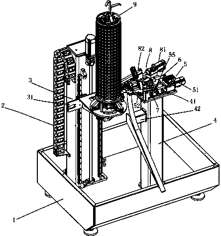
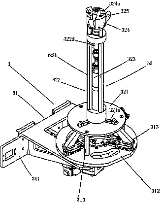
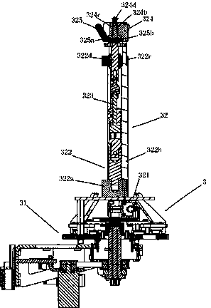
[0026] Such as Figure 1-7 Shown is an automatic hanging machine for electroplating parts of the present invention, including a chassis 1, a lifting mechanism 2, an electroplating hanger fixing device 3, a mounting table 4, a clamp compensation actuator 5, a hanging clamp 6, a two-dimensional video positioning device 7, Fixture compensation detection mechanism 8 and cage electroplating hanger 9, the lifting mechanism 2 is fixedly installed on the chassis 1, one side of the electroplating hanger fixing device 3 is clamped on the slide rail of the lifting mechanism 2 and it is also connected with the lifting mechanism 2 The lifting screw is threadedly connected, and the round cage electroplating hanger 9 is detachably arranged on the electroplating h...


PUM


Abstract

The invention discloses an automatic hanging machine for electroplates. The automatic hanging machine includes a base plate, a lifting mechanism, an electroplating hanging tool fixing device, a mounting table, a fixture compensation execution mechanism, a hanging fixture, a two-dimensional video positioning device, a fixture compensation detection mechanism and a round cage electroplating hangingtool, the lifting mechanism is fixedly installed on the base plate, the electroplating hanging tool fixing device is installed and arranged on the lifting mechanism, the round cage electroplating hanging tool is arranged on the electroplating hanging tool fixing device, the mounting table is fixedly installed on the base plate, and a mounting plate is formed at the end of the mounting table; the fixture compensation execution mechanism is fixedly installed on the mounting plate, and the hanging fixture is installed and arranged on the fixture compensation execution mechanism; and the two-dimensional video positioning device is installed and arranged at the position, located on one side of the hanging fixture, of the mounting plate, and the fixture compensation detection mechanism is installed and arranged at the position, located on the other side of the hanging fixture, of the mounting plate. The automatic hanging machine has the characteristics of continuous and automated removal ofthe electroplates in large quantities, high precision, stable performance, fast hanging speed of the electroplates and convenient maintenance.

Description

technical field [0001] The invention belongs to the technical field of electroplating parts production equipment, and in particular relates to an automatic hanging machine for electroplating parts. Background technique [0002] The production process of electroplated parts needs to be electroplated on the surface. During electroplating, a large number of electroplated parts are fixed on the electroplating rack of the cage. After the electroplating is completed, the electroplated parts are removed. The electroplating parts on the cage electroplating rack are removed, and in order to protect the quality of the electroplating parts, the removal process needs to be carried out one by one, so this will not only increase the labor cost of electroplating production, but also the hanging efficiency of the electroplating parts is very low. However, the current electroplating parts production equipment industry does not yet have high-precision equipment that can automatically batch an...

Claims


Application Information

Patent Timeline
IPC IPC(8): C25D17/08C25D21/00
CPCC25D17/08C25D21/00
Inventor 梁东昭南斌魏
Owner 佛山市领先智能装备有限公司
Features
  • R&D
  • Intellectual Property
  • Life Sciences
  • Materials
  • Tech Scout
  • Unparalleled Data Quality
  • Higher Quality Content
  • 60% Fewer Hallucinations
Learn More