Steel rail lifting apparatus for track construction track laying, and application method thereof

An application method and rail technology, applied in the direction of track, track laying, track maintenance, etc., can solve the problems of difficult ballastless track laying and accurate alignment, difficulty, and high precision, so as to improve laying efficiency, simple and reasonable device structure, Ease of manufacture and handling

Pending Publication Date: 2020-04-10
CHINA RAILWAY 24TH BUREAU GRP
View PDF0 Cites 2 Cited by
  • Summary
  • Abstract
  • Description
  • Claims
  • Application Information

AI Technical Summary

Problems solved by technology

However, the laying requires high precision and great difficulty. Considering factors such as the uneven road surface on the line and passing through bridges and tunnels, it is difficult to complete ballastless track laying and accurate alignment in a small space by using general cranes or traditional gantry cranes. bit

Method used


Image

  • Steel rail lifting apparatus for track construction track laying, and application method thereof
  • Steel rail lifting apparatus for track construction track laying, and application method thereof
  • Steel rail lifting apparatus for track construction track laying, and application method thereof

Examples


Embodiment 1

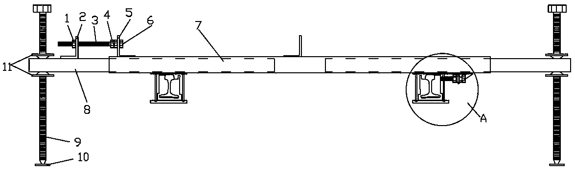
[0024] Embodiment one: if figure 1 As shown, in the rail lifting device used in track construction and laying provided by this embodiment, the main part of the device includes an outer sliding tube 7, an inner tube 8, an adjustable support and a bracket. Wherein, the two ends of the outer sliding tube 7 are respectively provided with an inner tube 8, the inner part of the inner tube 8 is partially sleeved inside the outer sliding tube 7, and the outer part protrudes outside the outer sliding tube 7; the inner tube 8 and the outer sliding Sliding fit is formed between the tubes 7 , that is, the inner tube 8 can protrude outward or retract inward along the extension direction of the tube body of the outer sliding tube 7 . The outer end of the inner tube 8 is connected with an adjustable support. The bracket is arranged at the bottom of the outer sliding tube 7 and is located at both ends of the outer sliding tube 7, and there is a bearing space for the rail in the bracket.

[...

Embodiment 2

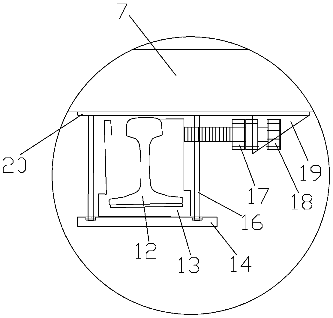
[0039] Embodiment 2: Compared with Embodiment 1, this embodiment differs in that: Figure 4 or Figure 5 As shown, in this embodiment, a fine-tuning sliding device is arranged between the outer sliding tube 7 and the bracket. Specifically, one or two fine-tuning nuts 21 are movable at the bottom of the outer sliding tube 7, and an oblong hole is arranged on the top plate 20. The oblong hole is located directly below the fine-tuning nuts 21. Fitting connection, the metal bolt head 22 is fixed on the bottom of the outer sliding tube 7 by tightening the connecting thread between the fine-tuning nut 21 and the metal bolt head 22, and the metal bolt is fixed by loosening the connecting thread between the fine-tuning nut 21 and the metal bolt head 22 The head 22 and the fine adjustment nut 21 can move left and right.

[0040] Such as Figure 5 As shown, the upper part of the metal bolt head 22 is provided with a thread matched with the fine-tuning nut 21, and the lower part of th...


PUM


Abstract

The invention relates to the technical field of track laying devices, and especially relates to a steel rail lifting apparatus for rail construction rail laying, and an application method thereof. Theapparatus comprises an outer sliding pipe, an inner pipe, an adjustable support and brackets, the adjustable support is used for adjusting the overall height of the inner pipe and the outer sliding pipe, a lateral movement locking device is arranged between the outer sliding pipe and the inner pipe, the lateral movement locking device can lock the relative position between the outer sliding pipeand the inner pipe so as to adjust the horizontal position of the steel rail, a pushing device is arranged in the lateral direction of at least one bracket, and the pushing device adjusts the positions of the steel rails in the brackets so as to adjust the distance between the steel rails in the two brackets. The apparatus has the advantages of completion of ballastless track laying and accurate alignment in a narrow space, remarkable improvement of the steel rail laying precision, improvement of the steel rail laying efficiency, simple and reasonable structure, and convenience to use, manufacture and carry.

Description

technical field [0001] The invention relates to the technical field of track laying devices, in particular to a rail lifting device used in track construction and laying and an application method thereof. Background technique [0002] In recent years, with the rapid development of my country's high-speed railway, passenger dedicated line and intercity rail transit, ballastless track has been widely used. However, the laying requires high precision and great difficulty. Considering factors such as the uneven road surface on the line and passing through bridges and tunnels, it is difficult to complete ballastless track laying and accurate alignment in a small space by using general cranes or traditional gantry cranes. bit. Therefore, need badly a kind of novel device to solve the above-mentioned problem. Contents of the invention [0003] The object of the present invention is to provide a rail lifting device and its application method for rail construction and rail laying...

Claims


Application Information

Patent Timeline
Patent Type & Authority Applications(China)
IPC IPC(8): E01B29/16E01B29/22E01B29/20
CPCE01B29/16E01B29/20E01B29/22
Inventor 戴春毅戴志增刘长春吴庆润叶盛旺刘新功蒋萌陈仕雄
Owner CHINA RAILWAY 24TH BUREAU GRP
Why Eureka
Try Eureka