Roller blind balance regulator and roller blind with same

A regulator and roller blind technology, applied in the direction of balance weight, spring/shock absorber, vibration suppression adjustment, etc., can solve the problems of inconvenient production, increased inventory, affecting the use of roller blinds, etc., and achieve good results

Pending Publication Date: 2020-04-10
GUANGZHOU JADY WINDOW COVERINGS TECH CO LTD
View PDF0 Cites 4 Cited by
  • Summary
  • Abstract
  • Description
  • Claims
  • Application Information

AI Technical Summary

Problems solved by technology

The hand-push roller blind system is realized under the condition of spring preload. During use, as the curtain body rises or falls, the elastic force of the spring on the roller blind rod is different. In long-term use, each zero When the transmission force of accessories changes, the torque will be difficult to balance, which seriously affects the use of roller blinds
Therefore, the current roller blind system on the market must be customized according to different widths, heights, and even different fabrics. This will result in a large number of specifications, increased inventory, and inconvenient production.

Method used


Image

  • Roller blind balance regulator and roller blind with same
  • Roller blind balance regulator and roller blind with same
  • Roller blind balance regulator and roller blind with same

Examples


Embodiment 1

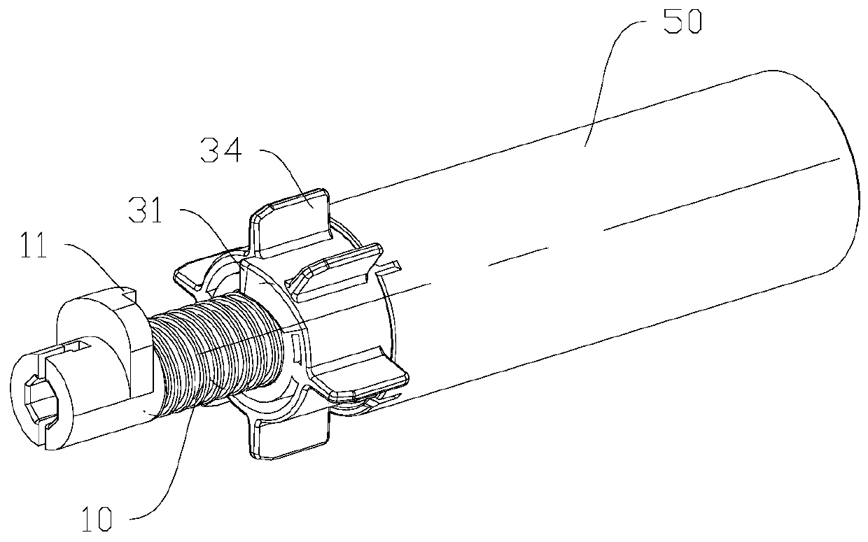
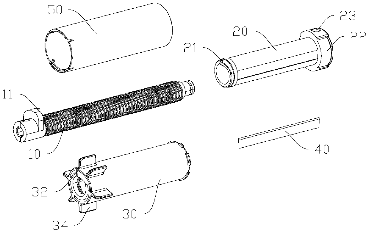
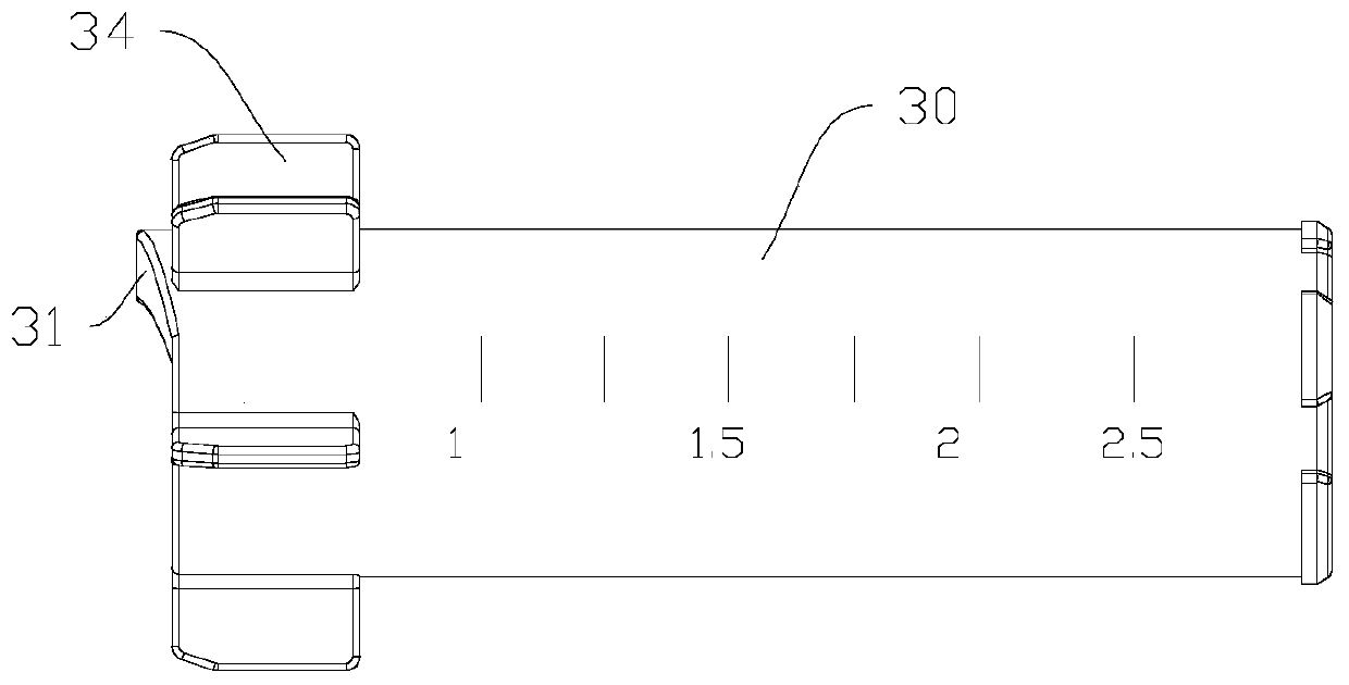
[0029] refer to Figure 1 to Figure 4 , the roller blind balance regulator in this embodiment includes a limit screw 10 , a mandrel 20 and a friction cylinder 30 . The mandrel 20 is provided with a mandrel through hole along the axial direction, and the limit screw 10 passes through the mandrel through hole and is fixed therein. An annular protrusion 22 is provided on the outside of the second end of the mandrel 20 , and at least one countersunk screw hole 23 is provided on the annular protrusion 22 , and the hole axis of the countersunk screw hole 23 is perpendicular to the limit screw 10 . The annular protrusion 22 can be integrally formed with the mandrel 20 . The bolt is screwed into the countersunk screw hole 23 , and the bottom end of the bolt abuts against the limit screw 10 , thereby fixing the relative position of the mandrel 20 and the limit screw 10 . The mandrel 20 is inserted into the friction cylinder 30. Preferably, the inside of the friction cylinder 30 is pr...

Embodiment 2

[0039] refer to Figure 5 , the roller blind balance adjuster in this embodiment differs from the first embodiment only in that the mandrel 20 and the limit screw 10 together form an integrally formed stepped shaft. The small-diameter end of the stepped shaft is provided with threads, the friction cylinder 30 is threadedly connected with the small-diameter section of the stepped shaft, and a friction layer is arranged between the friction cylinder 30 and the large-diameter section of the stepped shaft. This setting can avoid the abrasion caused by the mutual collision between the mandrel 20 and the limit screw 10, and simplify the structure.

Embodiment 3

[0041] refer to Figure 6 , the roller blind balance adjuster in this embodiment, which includes a fixing piece 60 and a friction cylinder 30 for connecting with a roller blind rod. The fixing member 60 includes a sleeve 62 and a central rod 61 fixed in the sleeve 62, the central rod 61 is arranged along the axial direction of the sleeve 62, and a space capable of accommodating the insertion of the friction cylinder 30 is formed between the sleeve 62 and the central rod 61 . Optionally, the central rod 61 and the sleeve 62 can be integrally formed. The friction cylinder 30 has an inner surface and an outer surface, one of the sides of the friction cylinder 30 is screwed to the fixing member 60 , and a friction layer is provided between the other side of the friction cylinder 30 and the fixing member 60 . The friction cylinder 30 is inserted into the space between the sleeve 62 and the central rod 61 , and the central rod 61 passes through the friction cylinder 30 . Optional...


PUM


Abstract

The invention discloses a roller blind balance regulator and a roller blind with the same. The roller blind balance regulator comprises a stepped shaft and a friction drum; the stepped shaft is provided with an external screw thread; the stepped shaft penetrates through the friction drum; the friction drum is provided with an internal screw thread; the friction drum is in threaded connection withthe stepped shaft; and a friction layer is arranged between the friction drum and the stepped shaft. The roller blind comprises a roller blind rod, fabric, two mounting members and the roller blind balance regulator, wherein a return spring is arranged in the roller blind rod. The roller blind rod drives the friction drum to rotate, the friction drum moves in the axial direction of a limiting threaded rod while the friction drum rotates, and thus the friction force between the friction drum and a friction layer is increased or decreased. When the roller blind rod rotates, the friction force between the friction drum and the friction layer can be increased or decreased along with change of torque of the return spring, and thus the function of dynamically balancing the return spring is achieved. By means of the roller blind balance regulator and the roller blind with the same, the torque of the return spring can be balanced better, the friction force between the friction drum and the friction layer can dynamically compensate the torque difference of the return spring, and the using effect is good.

Description

technical field [0001] The invention relates to a roller blind balance adjuster in the technical field of household articles and a roller blind composed of the same. Background technique [0002] Roller roller blinds are more and more used by people, but children often bring some safety hazards because of the beads. In some places, bead roller blinds are difficult to install and inconvenient to operate, but they cannot increase the cost of installing electric roller blinds, and in some places there is no power supply. In order to solve these problems, the demand for push roller shutter systems is increasing. The hand-push roller blind system is realized under the condition of spring preload. During use, as the curtain body rises or falls, the elastic force of the spring on the roller blind rod is different. In long-term use, each zero When the transmission force of accessories changes, the torque will be difficult to balance, which seriously affects the use of roller blind...

Claims


Application Information

Patent Timeline
Patent Type & Authority Applications(China)
IPC IPC(8): E06B9/42E06B9/62
CPCE06B9/42E06B9/62E06B9/90E06B9/60
Inventor 邱永忠
Owner GUANGZHOU JADY WINDOW COVERINGS TECH CO LTD
Why Eureka
Try Eureka