Acquisition method of laser resistance trimming scheme, laser resistance trimming scheme and chip resistor

A technology of laser resistance adjustment and acquisition method, which is applied to non-adjustable metal resistors, resistors, resistance manufacturing and other directions, can solve the problems of low resistance precision and low yield, and achieves the improvement of controllability, precision and yield. Effect

Active Publication Date: 2020-04-10
SHENZHEN JPT OPTO ELECTRONICS CO LTD
View PDF3 Cites 3 Cited by
  • Summary
  • Abstract
  • Description
  • Claims
  • Application Information

AI Technical Summary

Problems solved by technology

[0005] The first purpose of the present invention is to provide a method for obtaining a laser resistance adjustment scheme, so as to obtain a method that can solve the low resistance accuracy and low yield of the secondary resistance adjustment method commonly found in the current secondary resistance adjustment method to a certain extent. Laser Trimming Solution for Technical Problems

Method used


Image

  • Acquisition method of laser resistance trimming scheme, laser resistance trimming scheme and chip resistor
  • Acquisition method of laser resistance trimming scheme, laser resistance trimming scheme and chip resistor
  • Acquisition method of laser resistance trimming scheme, laser resistance trimming scheme and chip resistor

Examples


Embodiment 1

[0058] The method for obtaining a laser resistance trimming solution provided in this embodiment is used to obtain a laser resistance trimming method.

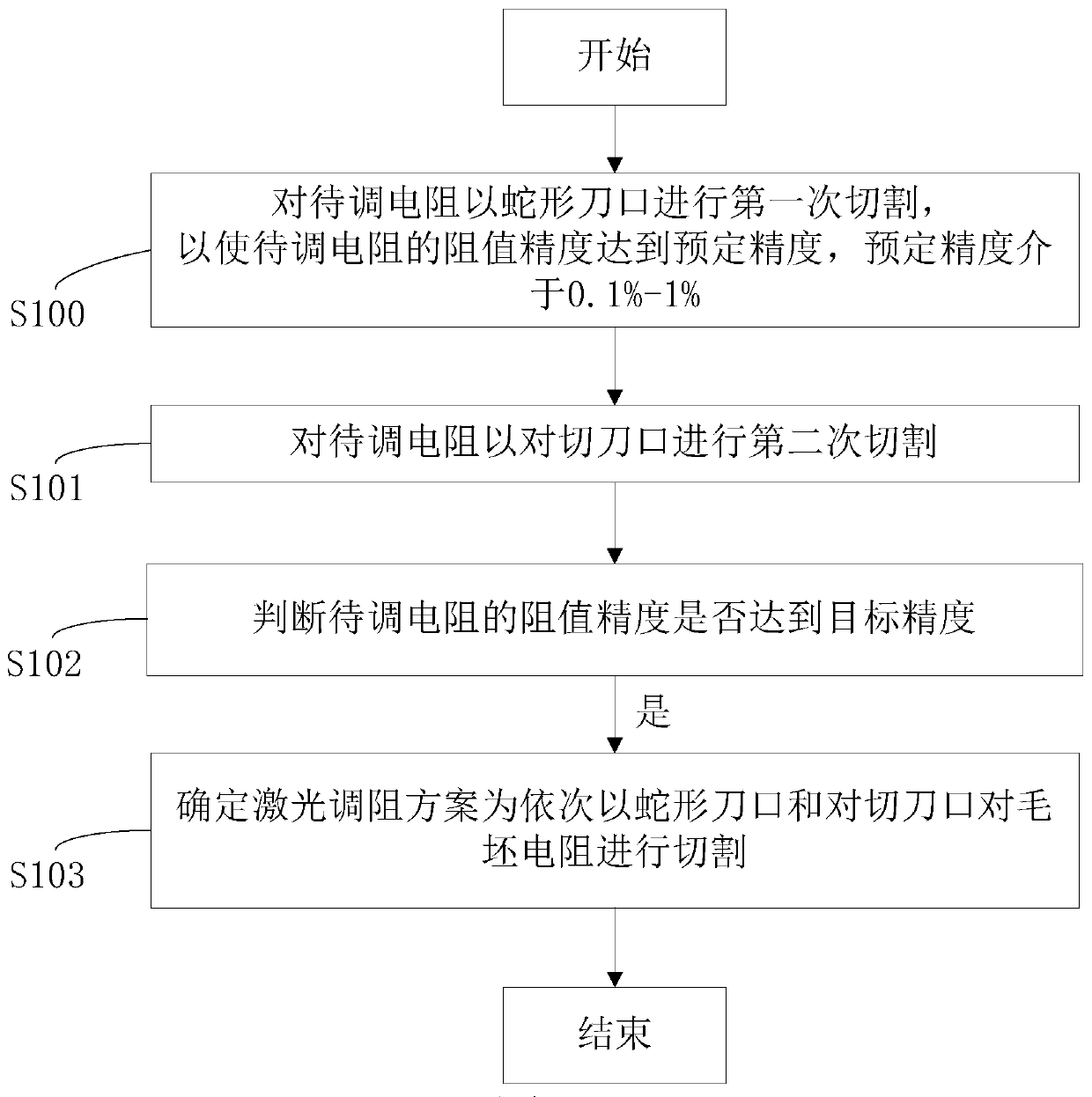
[0059] see figure 1 As shown, the method for obtaining the laser resistance trimming solution provided in this embodiment includes the following steps:

[0060] S100, cut the resistance to be adjusted for the first time with a serpentine knife edge, so that the resistance accuracy of the resistance to be adjusted can reach the predetermined accuracy, and the value range of the predetermined accuracy is 0.1%-1%;

[0061] S101, adjust the resistance to perform a second cut on the cutting edge;

[0062] S102, judging whether the resistance precision of the resistor to be adjusted reaches the target precision;

[0063] S103, if the resistance accuracy of the resistor to be adjusted reaches the target accuracy, determine the laser resistance adjustment solution as cutting the blank resistor with a serpentine edge and a counter-cu...

Embodiment 2

[0126] Embodiment 2 provides a laser resistance trimming solution, which includes the acquisition method of the laser resistance trimming solution in Embodiment 1, and the technical features of the laser resistance trimming solution acquisition method disclosed in Embodiment 1 are also applicable to this implementation For example, the technical features of the method for obtaining the disclosed laser resistance trimming solution in Embodiment 1 will not be described repeatedly.

[0127] The laser resistance trimming solution provided in this embodiment is obtained by the method for obtaining the laser resistance trimming solution provided in Embodiment 1.

[0128] Specifically, the laser resistance trimming solution includes the following steps:

[0129] S700, for the first cutting of the blank resistor with a snake-shaped knife edge, so that the resistance precision of the resistor to be adjusted can reach the predetermined precision;

[0130] S701, performing a second cut ...


PUM


Abstract

The invention relates to the technical field of laser resistance trimming, in particular to an acquisition method of a laser resistance trimming scheme, the laser resistance trimming scheme and a chipresistor. The acquisition method of the laser resistance trimming scheme comprises the following steps that a to-be-trimmed resistor is subjected to primary cutting through a serpentine knife edge, so that the resistance value precision of the to-be-trimmed resistor reaches the preset precision, and the value range of the preset precision is 0.1%-1%; the to-be-trimmed resistor is subjected to secondary cutting through the cutter edge; it is judged whether the resistance precision of the to-be-trimmed resistor reaches the target precision or not; and if the resistance precision of the to-be-trimmed resistor reaches the target precision, it is determined that the laser resistance trimming scheme is that the blank resistor is cut by the serpentine knife edge and the bisection knife edge in sequence. The laser resistance trimming scheme is obtained by adopting the obtaining method of the laser resistance trimming scheme. The chip resistor is produced through the laser resistance adjustingscheme. According to the acquisition method of the laser resistance trimming scheme, the laser resistance trimming scheme and the chip resistor, the precision and the yield of the finished resistor can be improved.

Description

technical field [0001] The invention relates to the technical field of laser resistance trimming, in particular to a method for obtaining a laser resistance adjustment scheme, a laser resistance adjustment scheme and a chip resistor. Background technique [0002] The principle of laser trimming is to use a very thin laser beam to hit the thick and thin film resistors, and the resistor body is vaporized and evaporated to realize the cutting of thick and thin film circuits. By changing the conductive cross-sectional area of ​​the resistors, the resistance accuracy is improved. [0003] In order to improve the resistance accuracy from 1% to 0.1%, laser repairing is usually performed by secondary resistance adjustment. After the first resistance adjustment operation, it is usually cut within the accuracy range of 1% to 1.5% of the target value, and then after the second resistance adjustment operation, it is cut within the accuracy range of 0.1% of the target value. [0004] Ho...

Claims


Application Information

Patent Timeline
Patent Type & Authority Applications(China)
IPC IPC(8): H01C17/242H01C7/00
CPCH01C17/242H01C7/00H01C7/003H01C7/006
Inventor 柯梽全陈德佳彭荣森成学平刘健黄治家
Owner SHENZHEN JPT OPTO ELECTRONICS CO LTD
Why Eureka
Try Eureka