Hanging type rainproof transformer
A transformer and hanging technology, which is applied in the field of hanging rain-proof transformers, can solve the problems of affecting the service life of the transformer, damage to the iron core, and being prone to rain, etc., and achieves easy installation and disassembly or maintenance, convenient and stable use good sex effect
- Summary
- Abstract
- Description
- Claims
- Application Information
AI Technical Summary
Problems solved by technology
Method used
Image

Examples
specific Embodiment approach 1
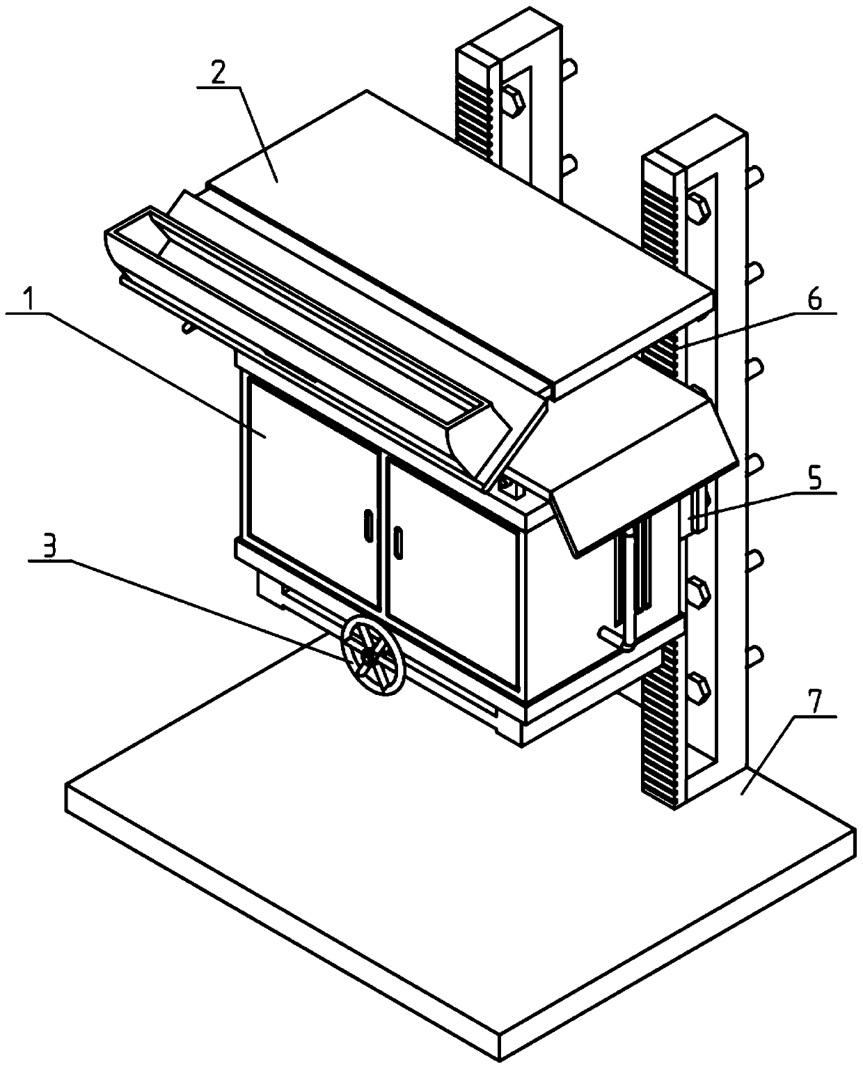
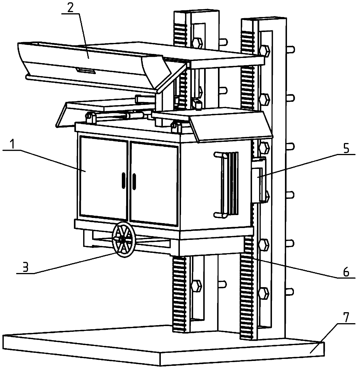
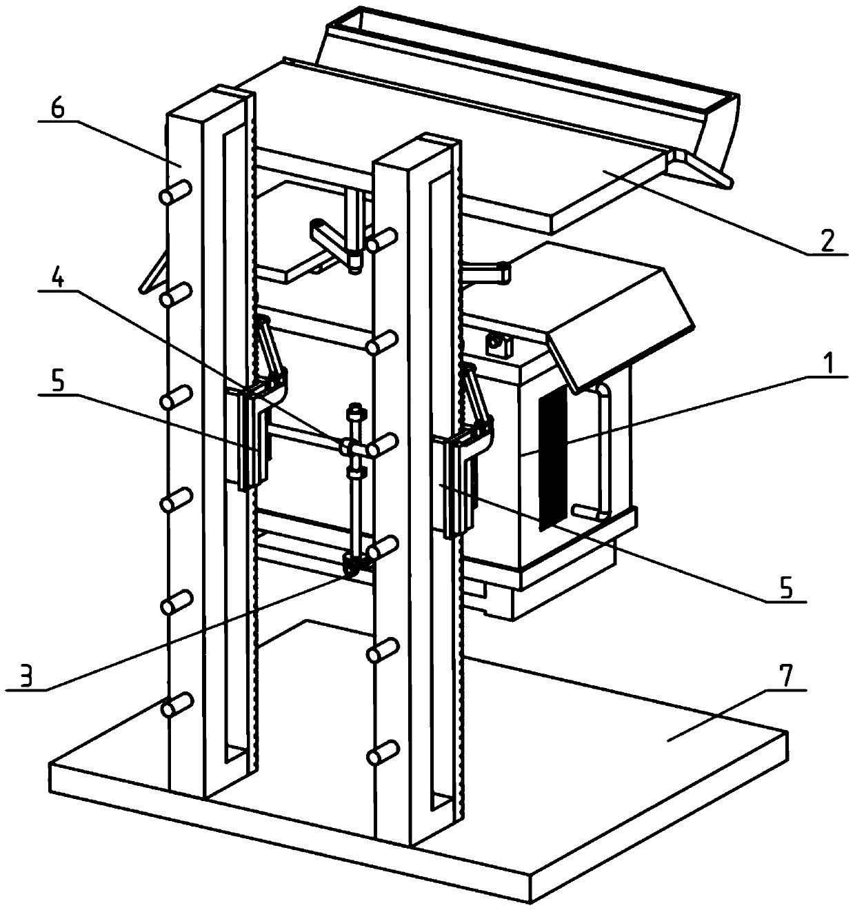
[0039] Such as Figure 1-13 As shown, the hanging rainproof transformer includes a transformer box 1 with a transformer body installed inside. The front side of the transformer box 1 is provided with a box door 101, and the left and right sides of the transformer box 1 are provided with cooling grooves 102. It also includes a rainproof cover 2, a lifting control part 3, a lifting transmission part 4, a lifting part 5, a hanger 6 and a base 7;
[0040] The top of the transformer box 1 is connected to the rainproof cover 2; the bottom of the transformer box 1 is connected to the lifting control member 3; the rear of the transformer box 1 is connected to the two side-by-side The lifting part 5 is connected; the lifting control part 3 is connected to the lifting part 5 through the lifting transmission part 4; the lifting transmission part 4 is connected to the rear part of the transformer box 1; the two The lifting member 5 is matedly connected to the two hangers 6 ; the two hang...
specific Embodiment approach 2
[0042] Such as Figure 1-13 As shown, the rainproof cover 2 includes a top cover 201, a central column 202, a tension spring 203, a spring seat 204, a sliding cover 205, an oblique block 206 and a water collection tank 207; the top cover 201 passes through the central column 202 It is fixed in the middle of the top of the transformer box 1; the front part of the top cover 201 is provided with a rectangular chute; the inner side of the rectangular chute is slidingly fitted to connect the sliding cover 205; the lower end of the sliding cover 205 is fixedly connected The spring seat 204; the tension spring 203 is fixedly connected between the spring seat 204 and the central column 202; the front end of the slide cover 205 is fixedly connected to the oblique block 206; The height of the rear part is higher than the height of the front part of the slant 206; the top of the slant 206 is provided with the water collecting tank 207; the middle part of the front side of the water colle...
specific Embodiment approach 3
[0044] Such as Figure 1-13 As shown, the rainproof cover 2 also includes a side cover 208, a side block 210, a chute frame 211, a transverse shaft 212, an axle seat 213, a sliding link 214 and a push-pull link 215; Two ends are respectively provided with a front and rear sliding hole, and the two front and rear sliding holes communicate with the rectangular chute; the rear end of the bottom surface of the top cover 201 is fixedly connected with the two sliding connecting rods 214, and the two sliding The connecting rod 214 is slidably fitted in the two front and rear slide holes, and the lower ends of the two sliding connecting rods 214 are respectively connected to the inner end of one of the push-pull connecting rods 215, and the outer ends of the two push-pull connecting rods 215 are connected to each other. One of the side covers 208 is rotationally connected; the lower ends of the two side covers 208 are respectively fixedly connected with one of the chute frames 211; th...
PUM
 Abstract
Description
Claims
Application Information
 - R&D Engineer
- R&D Manager
- IP Professional
- Industry Leading Data Capabilities
- Powerful AI technology
- Patent DNA Extraction
Browse by: Latest US Patents, China's latest patents, Technical Efficacy Thesaurus, Application Domain, Technology Topic.
© 2024 PatSnap. All rights reserved.Legal|Privacy policy|Modern Slavery Act Transparency Statement|Sitemap