Locking type inertia switch

An inertial switch and locking hole technology, applied in the field of inertial switches, can solve problems such as inaccurate control of inertial switch closing time, difficulty in realizing inertial switches, and poor contact reliability, so as to improve stability and reliability and avoid reset , to ensure a reliable matching effect

Active Publication Date: 2020-04-10
湖北三江航天红林探控有限公司
View PDF3 Cites 4 Cited by
  • Summary
  • Abstract
  • Description
  • Claims
  • Application Information

AI Technical Summary

Problems solved by technology

Although the above-mentioned inertial switch can meet the needs of use to a certain extent, it also has certain defects, mainly because the above-mentioned inertial switch often bounces off the mass block after the mass block collides with the fixed electrode, resulting in inaccurate control of the closing time of the inertial switch , and the contact reliability of the contacts is poor
In addition, in some products, in order to prevent accidental impact, it is often necessary to realize self-locking after the switch is closed to ensure the continuous and stable power connection of the switch and the stable operation of the power supply and load circuit, but this uses the existing inertial switch Often difficult to achieve, so that the application of the above products is limited

Method used


Image

  • Locking type inertia switch
  • Locking type inertia switch
  • Locking type inertia switch

Examples


Embodiment

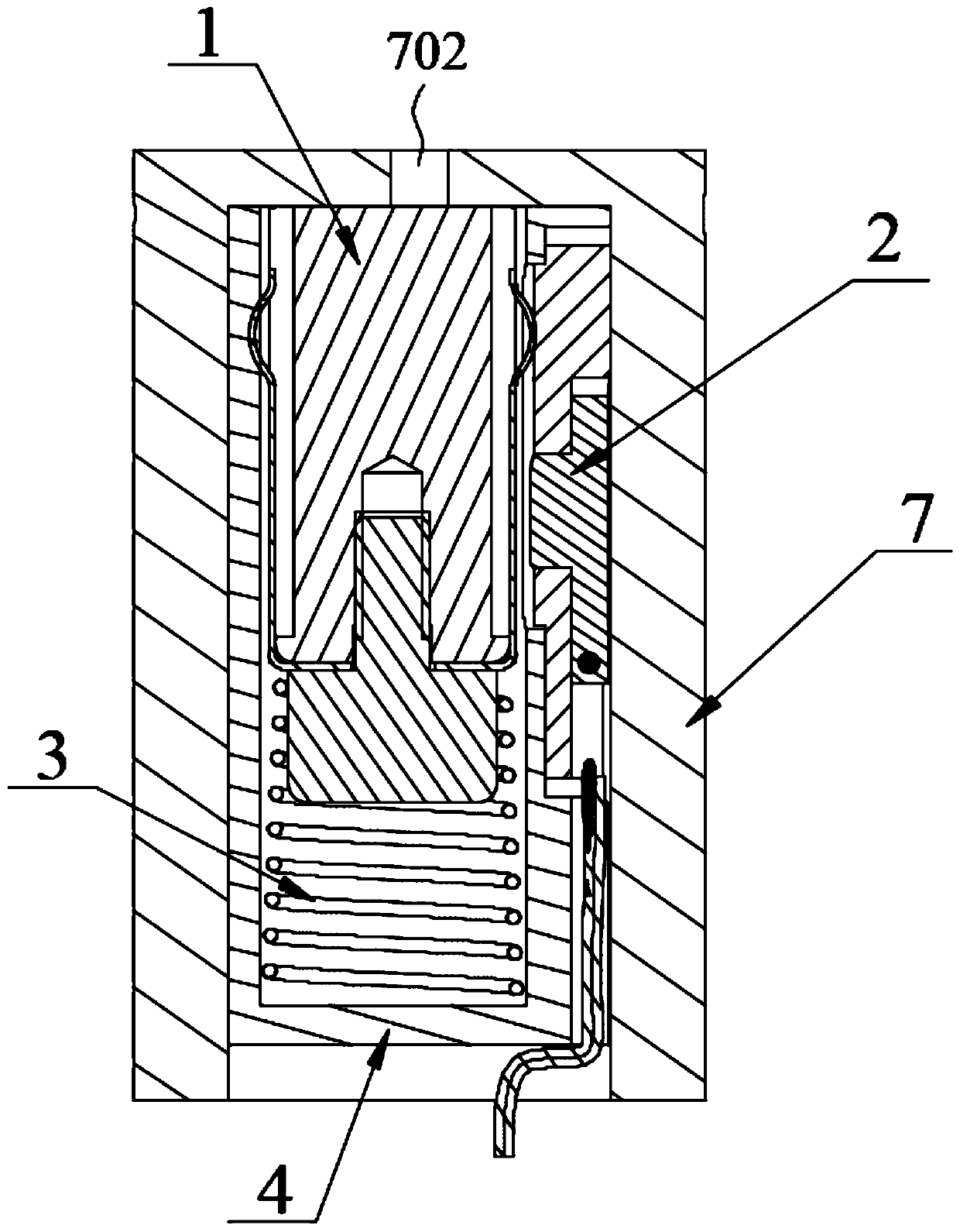
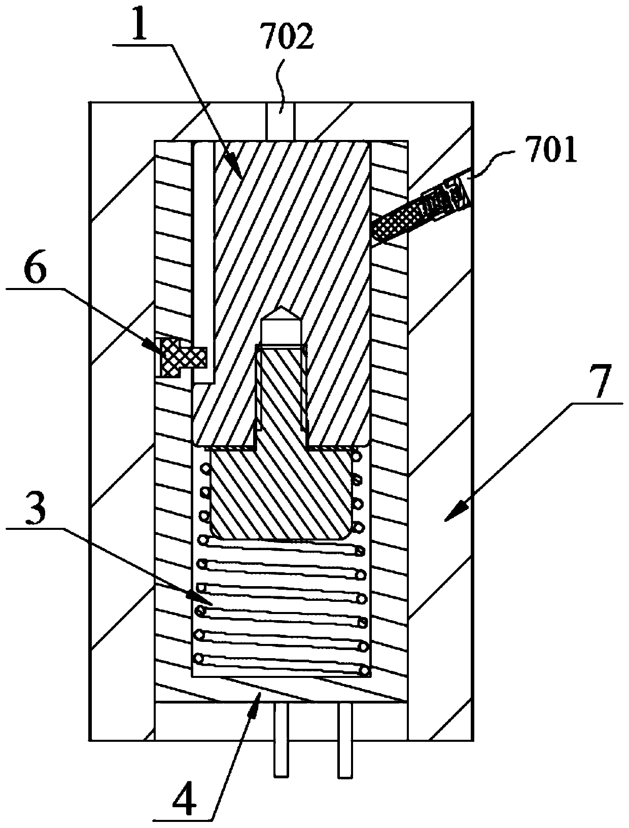
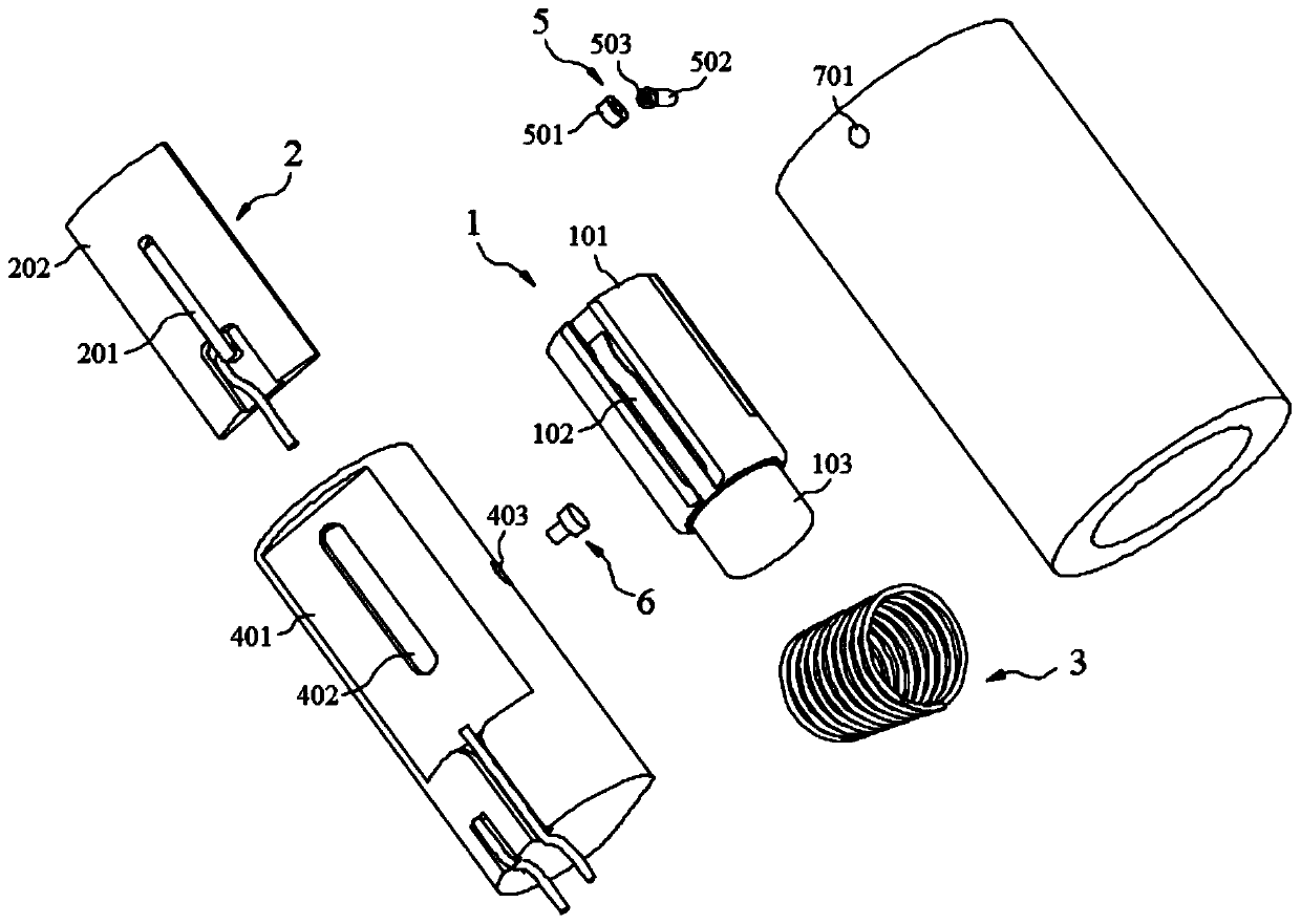
[0042] The latching type inertia switch in the preferred embodiment of the present invention is such as Figures 1 to 5 shown in. Among them, it includes a correspondingly matched movable electrode part 1 , a static electrode part 2 , an inertia spring 3 , a casing 4 , a locking part 5 , a guide pin 6 and a casing 7 .

[0043] Specifically, in the preferred embodiment, the shell 4 and the outer casing 7 are respectively cylindrical structures, and the cylindrical structures here may be cylindrical structures, square cylindrical structures, or other cylindrical structures. One end of the cylinder body is provided with a certain depth of blind holes along the axial direction, and the outer shape of the casing 4 corresponds to the blind holes opened on the outer casing 7 so that the casing 4 can be matched and embedded in the blind holes on the outer casing 7 . Preferably, in the preferred embodiment, the blind hole opened at one end of the casing 7 is a circular hole, that is, ...


PUM


Abstract

The invention discloses a locking type inertia switch, and belongs to the technical field of inertia switches. With the corresponding arrangement of a movable electrode component, a static electrode component and a locking part, the separation of the movable electrode from the static electrode when the movable electrode does not work and the stable and reliable matching of the movable electrode and the static electrode when the movable electrode works can be effectively realized, and through the corresponding arrangement of the locking part, the situation that the moving electrode part can belocked at the working position by the locking part after the moving electrode is matched with the static electrode, can be effectively guaranteed, and the situation that the moving electrode part resets caused by the overload reduction or overload disappearance, is avoided. The locking type inertia switch is simple in structure, good in working accuracy and high in reliability, is simple and convenient to assemble, can effectively avoid the unstable matching of the moving electrode and the static electrode, and realizes the reliable locking of the moving electrode and the static electrode after the moving electrode and the static electrode are matched. Moreover, the inertia switch is many in number of cycles and long in service life, enables the service life to be reduced effectively, promotes the application of the inertia switch, and has the better practical value and popularization value.

Description

technical field [0001] The invention belongs to the technical field of inertia switches, and in particular relates to a latched inertia switch. Background technique [0002] Inertial switches have a wide range of applications in aerospace, automotive electronics, and ammunition. In general, the inertia switch is closed by the reaction force or the forward impulse inertia force when the carrier hits the target, and realizes the function of the circuit from disconnection to connection. Inertial switches are widely used in fuzes, especially in electromechanical fuzes, and are important components for electromechanical fuzes to trigger detonation or self-destruct on the ground. [0003] At present, most of the existing inertia switches adopt a combined structure of a spring and a mass block. The spring and the mass block are used as movable electrodes and correspond to a fixed electrode separately provided and separated from the movable electrode at a certain distance. When th...

Claims


Application Information

Patent Timeline
Patent Type & Authority Applications(China)
IPC IPC(8): H01H35/14
CPCH01H35/141H01H35/143
Inventor 李响常江
Owner 湖北三江航天红林探控有限公司
Why Eureka
Try Eureka