Radio frequency plug and manufacturing method thereof

A plug and radio frequency technology, applied in the assembly/disassembly of contacts, antenna connectors, contact parts, etc., can solve the problems of radio frequency signal shielding, easy to cause looseness and misalignment, etc.

Pending Publication Date: 2020-04-10
KUNSHAN KTA COMM TECH CO LTD
View PDF1 Cites 0 Cited by
  • Summary
  • Abstract
  • Description
  • Claims
  • Application Information

AI Technical Summary

Problems solved by technology

[0003] In the 5G communication era, multi-antenna transmission is required, and the traditional single-channel RF connector can no longer meet the requirements; among the existing alternatives, there is a technical solution that uses board-to-board connectors to realize multi-channel transmission of antenna signals. One of the technical problems to...

Method used


Image

  • Radio frequency plug and manufacturing method thereof
  • Radio frequency plug and manufacturing method thereof
  • Radio frequency plug and manufacturing method thereof

Examples


Embodiment 1

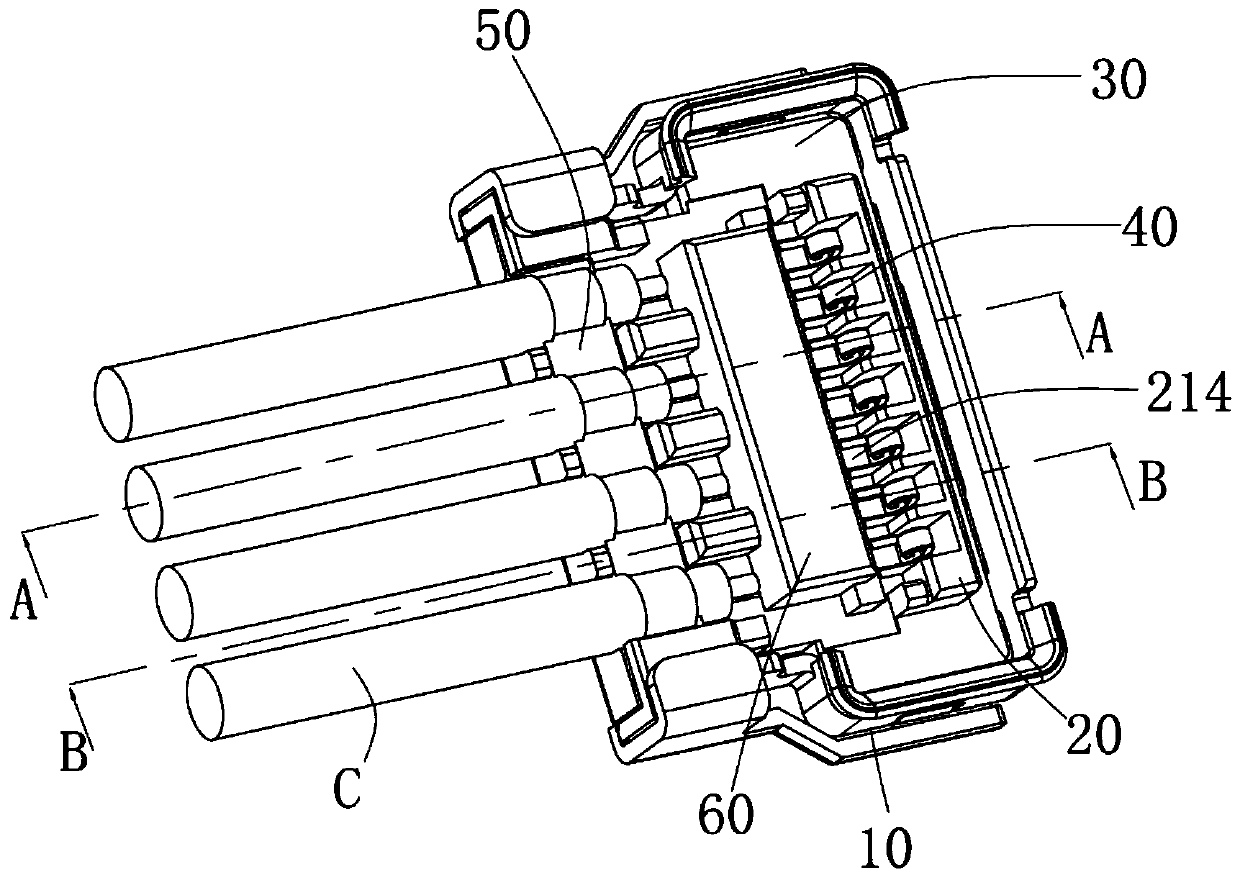
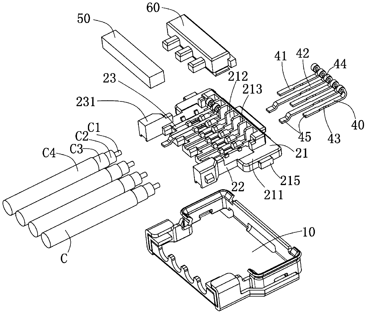
[0045] See Figure 1 to Figure 3 As shown, the radio frequency plug of this application includes a plug body 20, 60, a plurality of plug terminals 40 formed in the plug body 20, 60, a shielding shell 10 covering the plug body 20, and formed on the plug The insertion space 30 between the main body 20 and the shielding shell 10, a number of coaxial wires C connected to the plug terminal 40 and the conductive glue 50.

[0046] The coaxial wire C includes a central conductor C1, an inner insulating layer C2 covering the outer of the central conductor C1, a braided layer C3 covering the outer periphery of the inner insulating layer C2, and a braided layer C3 covering The outer insulating layer C4.

[0047] The plug body includes an insulating base body 20 and a molding block 60 formed on the insulating base body 20 to fix the plug terminal 40.

[0048] The insulating base body 20 includes a main body base 21, a terminal base 23 formed at the rear end of the main body base 21, a mating po...

Embodiment 2

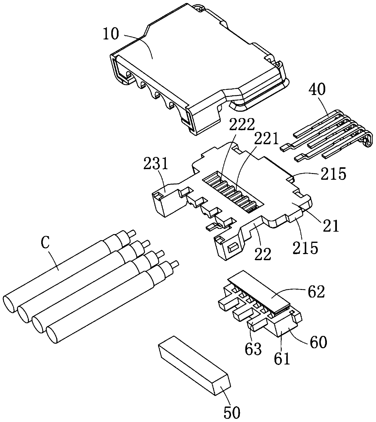
[0058] The second embodiment of the present application mainly introduces the molding structure and manufacturing method of the plug terminal 40, the insulating base body 20 and the molding block 60 in detail.

[0059] See figure 2 , Figure 7 , Figure 8 As shown, the terminal groove 212 of the insulating base body 20 extends from the protruding portion 213 back to the terminal base 23, and the terminal groove 212 is located at the position of the protruding portion 213 and is arranged between each other. The spacer 216 separates the terminal slot 212 into a space for the elastic contact arm 44 to deform. The terminal groove 212 is recessed downward at the positions of the body base 21 and the terminal base 23. The terminal groove 212 forms spacing bosses 223 on both lateral sides at the position of the filling groove 221, and the spacing bosses 223 are used to apply a certain force to the plug terminal 40 assembled in the terminal groove 212. On the portion 43, the spacing bo...

Embodiment 3

[0070] See Figure 13 to Figure 15 As shown, the radio frequency plug of this embodiment further includes four metal inserts 90 integrally formed on the platform portion 211 of the insulating base body 20 and the mating portion 231 and clamped on the coaxial cable C The upper welding tab 82 and the lower welding tab 81 on the upper and lower sides of the braided layer C3. The upper welding piece 82 is fixed to the rear end of the substrate 11 of the shielding shell 10 by welding, and the lower welding piece 81 is fixed to the second cladding portion 142 by spot welding.

[0071] The metal insert 90 includes two first inserts 91 embedded in the platform portion 211 and two second inserts 92 embedded in the mating portion 231. The thickness of the platform portion 211 is relatively thin, and the thickness of the first insert 91 is smaller than the thickness of the second insert 92. The first insert 91 includes a first embedded portion 911 embedded in the platform portion 211, a f...


PUM


Abstract

A radio frequency plug comprises a plurality of plug terminals, an insulating seat body which fixedly holds the plug terminals into a whole, and a shielding shell which wraps the insulating seat body.The shielding shell comprises a substrate covering the upper part of the insulating seat body, and a front end wall and a side wall covering the front side and the two transverse sides of the insulating seat body; and a metal insert is integrally formed in the insulating seat body, the metal insert comprises an embedding part embedded in the insulating seat body and a welding surface exposed on the upper surface of the insulating seat body, and the welding surface is welded and fixed with a substrate of the shielding shell. The invention further provides a manufacturing method of the radio frequency plug.

Description

Technical field [0001] This application relates to the field of radio frequency connectors, in particular to a radio frequency plug and a manufacturing method thereof. Background technique [0002] Existing mobile phone PCB boards usually have RF connectors connected to coaxial cables to transmit RF signals, such as antenna signals, high-frequency signals between different boards; [0003] In the 5G communication era, multi-antenna transmission is required, and the traditional single-channel radio frequency connector can no longer meet the requirements; among the existing alternatives, a technical solution using board-to-board connectors to achieve multi-channel transmission of antenna signals has emerged. One of the technical problems to be solved is the shielding problem of radio frequency signals. The People’s Republic of China Patent No. 201921357079.8 discloses a radio frequency plug, socket, and connector assembly. The radio frequency plug includes a plug terminal provided w...

Claims


Application Information

Patent Timeline
IPC IPC(8): H01R13/50H01R13/504H01R13/6581H01R13/02H01R43/20H01R43/24
CPCH01R13/02H01R13/50H01R13/504H01R13/6581H01R43/20H01R43/24H01R2201/02H01R2201/16
Inventor 张自财
Owner KUNSHAN KTA COMM TECH CO LTD
Why Eureka
Try Eureka