Radiator

A heat sink and accommodating cavity technology, which is applied in the direction of cooling/ventilation/heating transformation, electrical components, electrical equipment structural parts, etc., can solve the problems of different cooling medium flow rates and uneven heat dissipation

Pending Publication Date: 2020-04-10
ELECTRIC POWER RESEARCH INSTITUTE, CHINA SOUTHERN POWER GRID CO LTD +1
View PDF0 Cites 3 Cited by
  • Summary
  • Abstract
  • Description
  • Claims
  • Application Information

AI Technical Summary

Problems solved by technology

However, when the cooling medium enters the heat dissipation channels, the flow rate of the cooling medium into each heat dissipation channel will be different. For exampl

Method used


Image

  • Radiator
  • Radiator
  • Radiator

Examples


Embodiment Construction

[0020] The specific implementation manners of the present invention will be further described in detail below in conjunction with the accompanying drawings and embodiments. The following examples are used to illustrate the present invention, but are not intended to limit the scope of the present invention.

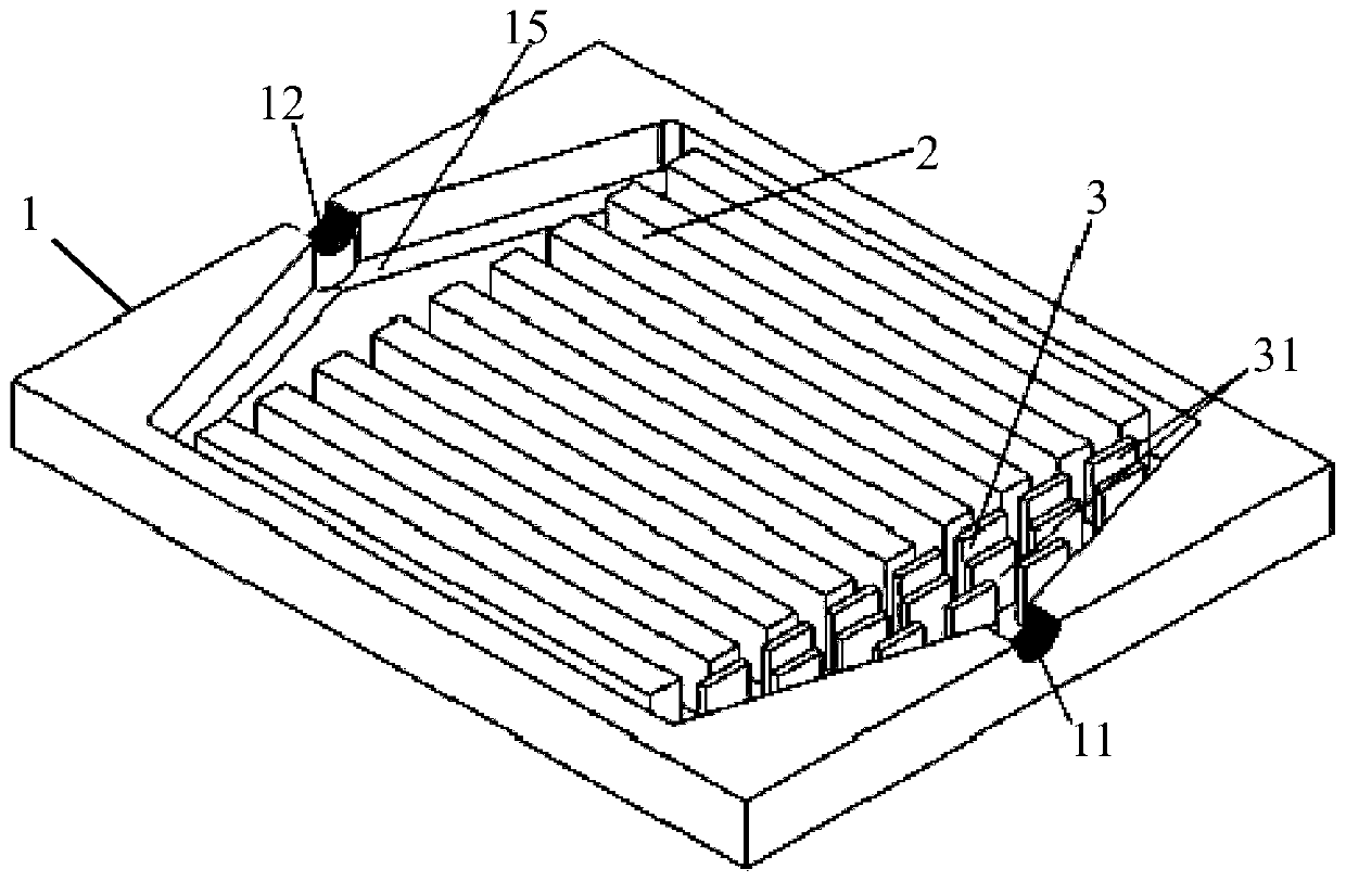
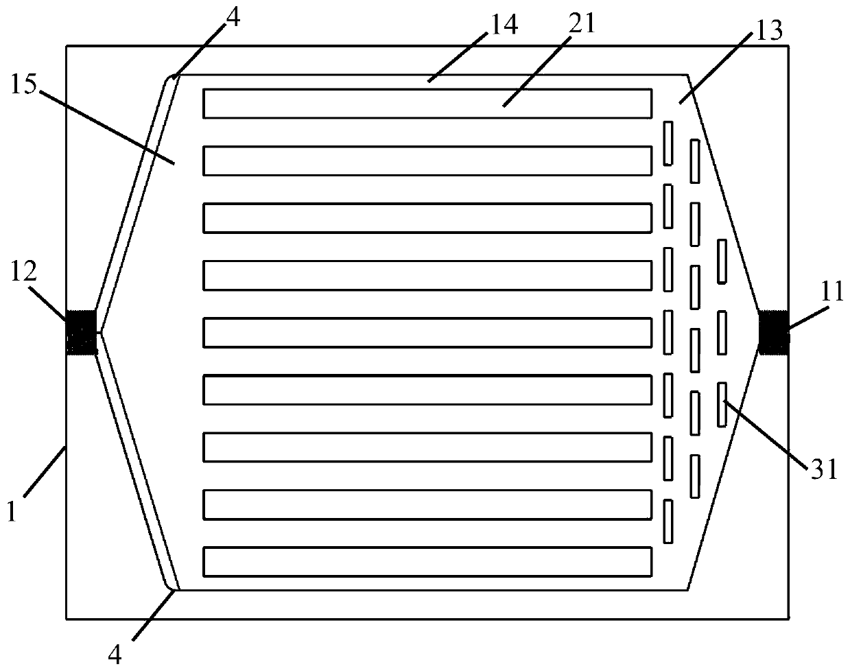
[0021] In the description of the present invention, directions such as up, down, left, right, front and back, and descriptions of top and bottom are all for image 3 As a limitation, when the placement of the radiator changes, its corresponding orientation and descriptions of the top and bottom will also change according to the change of placement, and the present invention will not repeat them here.

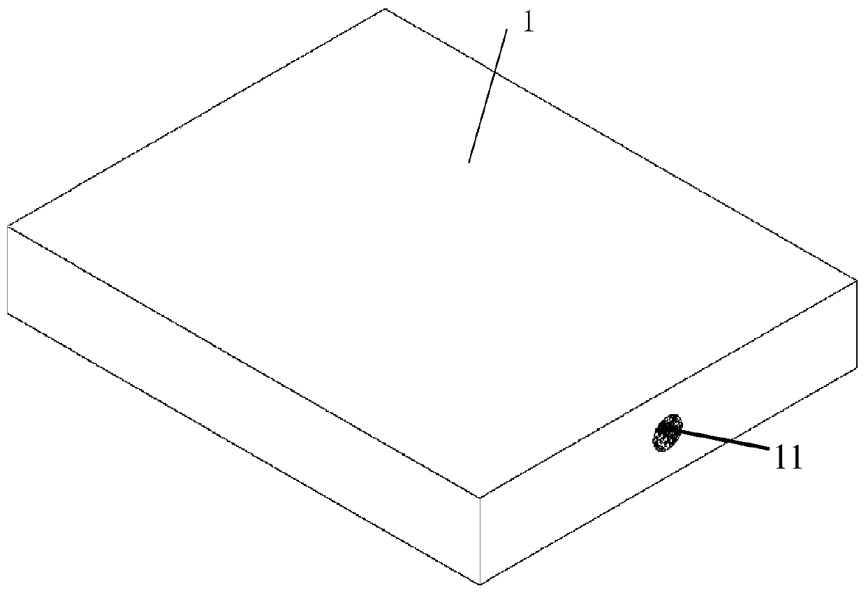
[0022] combine Figure 1 to Figure 3 As shown, a heat sink according to a preferred embodiment of the present invention includes a housing 1, a flow equalizing structure 3 and a flow channel structure 2, the housing 1 is provided with an inlet 11 and an outlet 12, and the h...


PUM


Abstract

The invention relates to the technical field of heat dissipation, and discloses a radiator. The radiator comprises a shell, a flow equalizing structure and a flow channel structure, wherein an inlet and an outlet are formed in the shell; a first containing cavity and a second containing cavity are formed in the shell, the first containing cavity communicates with the second containing cavity, theflow equalizing structure is arranged in the first containing cavity, the flow channel structure is arranged in the second containing cavity, the inlet communicates with the flow equalizing structure,and the flow equalizing structure communicates with the outlet through the flow channel structure. The flow channel structure comprises a plurality of heat dissipation flow channels. The flow equalizing structure comprises at least three spoilers which are sequentially arranged at intervals; a channel opening for a cooling medium to pass through is formed between every two adjacent spoilers, andafter entering the shell from the inlet, the cooling medium is shunted through the channel openings, so that the cooling medium can be uniformly shunted to the heat dissipation flow channels, and uniform heat dissipation is facilitated.

Description

technical field [0001] The invention relates to the technical field of heat dissipation, in particular to a radiator. Background technique [0002] A radiator is a device for exchanging heat with other equipment. At present, the existing radiator is generally provided with multiple heat dissipation channels, and the cooling medium exchanges heat with other equipment when passing through the multiple heat dissipation channels, thereby realizing heat dissipation for other equipment. However, when the cooling medium enters the heat dissipation channels, the flow rate of the cooling medium into each heat dissipation channel will be different. For example, the cooling medium will be concentrated in the middle flow channel, while the flow of the two side channels will be less, thus causing uneven heat dissipation. question. Contents of the invention [0003] The purpose of the embodiments of the present invention is to provide a heat sink, which can make the cooling medium more...

Claims


Application Information

Patent Timeline
IPC IPC(8): H05K7/20
CPCH05K7/20327H05K7/20936
Inventor 罗兵徐永生张福增罗炜曾向君廖一帆肖微王婷婷陈少杰卢威
Owner ELECTRIC POWER RESEARCH INSTITUTE, CHINA SOUTHERN POWER GRID CO LTD
Why Eureka
Try Eureka