Device and method for producing a molded pulp part and molded pulp part

A technology for molding parts and control devices is applied in the field of devices for manufacturing fiber molding parts to achieve the effect of expanding the filling volume

Inactive Publication Date: 2013-11-06
GRIMM SCHIRP GS TECH
View PDF10 Cites 5 Cited by
  • Summary
  • Abstract
  • Description
  • Claims
  • Application Information

AI Technical Summary

Problems solved by technology

[0003] The problem with producing fiber moldings in this way is that the fiber moldings should have an elastic effect perpendicular to the main load direction, especially in the case of relatively flat 3D moldings such as seat cushions or seat backrests

Method used


Image

  • Device and method for producing a molded pulp part and molded pulp part
  • Device and method for producing a molded pulp part and molded pulp part
  • Device and method for producing a molded pulp part and molded pulp part

Examples


Embodiment Construction

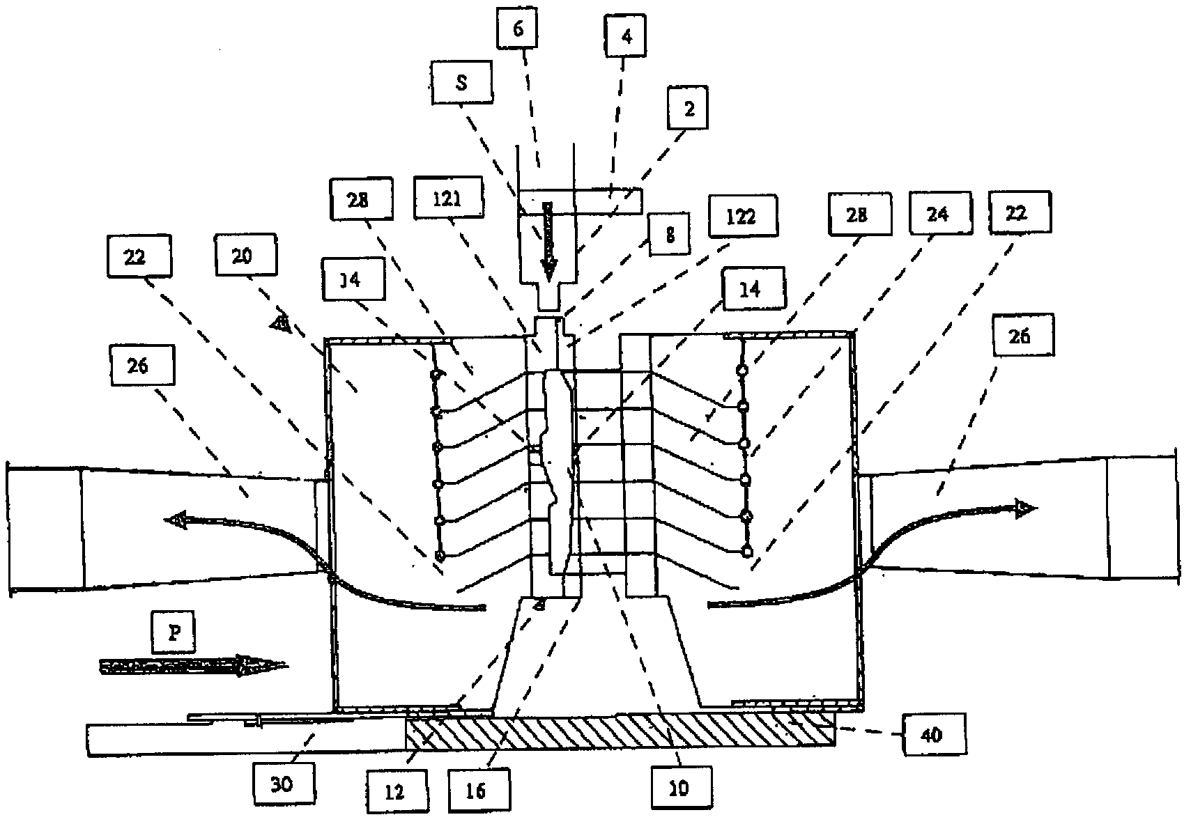
[0042] exist figure 1 A device for producing fiber moldings is shown in schematic cross-section in . The device has a fiber delivery device 2 in the form of a filler neck, which is equipped with a heating device and a heat exchanger 6 . The fibers to be introduced into the mold 12 are provided in the filling nozzle of the fiber feed device 2 and are introduced pneumatically via the introduction opening 8 shown schematically in the region of the parting line of the mold 12 Mold 12. The mold 12 consists of two mold parts 121 , 122 which are arranged on the tool receiver. There may also be more than two mold parts. The left mold part 121 and its associated tool holder are mounted displaceably on the slide 30 on the frame 40 . A pressure P can be applied via the slide 30 in order to displace the left mold part 121 in the direction of the right mold part 122 . It is likewise possible to move the mold parts 121 , 122 away from each other in order to increase the volume of the c...


PUM


Abstract

The invention relates to a device for producing a molded pulp part (10), comprising a pneumatic fiber feeding apparatus (2) having an associated heating apparatus (4) having at least one heat exchanger (6) for heating up heating air and a mold (12), which has through-flow holes (14) for the transport air on at least one side, wherein the mold (12) has an outlet controller (20) arranged on the side of the through-flow holes (14), said outlet controller having a plurality of outlet openings (22), which can be closed and which are arranged one behind the other in the feeding direction of the fibers.

Description

technical field [0001] The invention relates to a device and a method for producing fiber molded parts, the device having a pneumatic fiber feed device and a mold, the pneumatic fiber feed device having an associated heating device with at least one For the heat exchanger for heating the heating air, the mold has, on at least one side, throughflow holes for conveying the air. The invention likewise relates to a fiber molded part made of a thermally crosslinkable fiber material which crosslinks in a corresponding manner with the introduction of thermal energy, wherein the fiber molded part has relatively The upper side is oriented perpendicularly to the main load direction of the fiber molding. The device, the method and the fiber molding itself are particularly suitable for producing three-dimensional mats or components which, in addition to sufficient stability in the main load direction, also have sufficient form stability. Background technique [0002] Fiber moldings ca...

Claims


Application Information

Patent Timeline
Patent Type & Authority Applications(China)
IPC IPC(8): D04H1/542
CPCB29C70/46D04H1/542B29C2043/3455B29C43/34B29C70/16D04H1/732B29C41/36B29K2267/00B29L2031/58B29K2021/003D04H13/00B29K2311/10Y10T442/643
Inventor H·格林
Owner GRIMM SCHIRP GS TECH
Why Eureka
Try Eureka