Plastic oiling plant for converting plastic waste into petrochemical products, corresponding cracking reactor and associated method

A technology of cracking reactor and chemical equipment, which is applied in chemical instruments and methods, preparation of liquid hydrocarbon mixtures, petroleum industry, etc., can solve problems such as limiting the maximum capacity of the reactor, save non-renewable raw materials, and achieve fast and uniform heating. , to avoid the effect of carbonization

Active Publication Date: 2022-01-14
PRUVIA GMBH
View PDF7 Cites 5 Cited by
  • Summary
  • Abstract
  • Description
  • Claims
  • Application Information

AI Technical Summary

Problems solved by technology

The limited diameter that allows for a flat temperature profile severely limits the maximum capacity of the reactor

Method used


Image

  • Plastic oiling plant for converting plastic waste into petrochemical products, corresponding cracking reactor and associated method
  • Plastic oiling plant for converting plastic waste into petrochemical products, corresponding cracking reactor and associated method
  • Plastic oiling plant for converting plastic waste into petrochemical products, corresponding cracking reactor and associated method

Examples


Embodiment Construction

[0074] The invention is based on the following general observations.

[0075] Plastic waste: market and cost.

[0076] Originally involved in the plastic waste market: Today, small sections are actually sent to mechanical recovery plastics is limited to PET (polyethylene terephthalate) and HDPE (high density polyethylene). The remainder of the polyolefin such as LDPE (low density polyethylene), PP (polypropylene) or polystyrene (PS) market situation is not good and its value is low. All processed polymers, those polymers including heteroatom (oxygen, nitrogen, chlorine, sulfur ...), and other substances are destined to perform energy recovery after the addition of other waste (second fuel).

[0077]Correctly designed the key points of chemical treatment equipment and the plastic source for the feed of chemical processes: how the plastic source must consist, through which polymer is composed, what is the proportion; where to get and how to get, how many garbage Pouring the fee to ...


PUM


Abstract

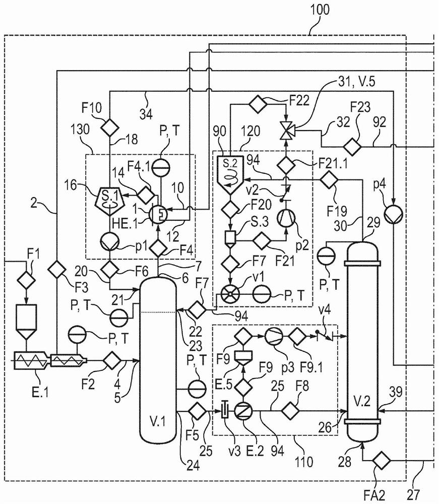
A plastic oiling plant for converting plastic into petrochemical products will be easy to build, easy to operate and easy to maintain. Operation will be energy and resource efficient. In order to achieve this object, the invention provides a system for the oiling of plastics, comprising a cracking reactor (V.1) for a pyrolysis reaction, in which plastics, in particular polyolefins, are converted into at least gasified pyrolysis products and scorched products, and further comprising a separate burner (V.2), the cracking reactor (V.1) comprises a plastic inlet port, in particular a plastic melt inlet port (5), a pellet inlet port (23), a pyrolysis product outlet port (6) and a scorch and pellet outlet port (24), and the burner (V.2) comprises a scorch and pellet inlet port (26), a combustion air inlet port (28) and a combustion product and pellet outlet port (29), the scorch and particle outlet port (24) of the cleavage reactor (V.1) is connected to the scorch and particle inlet port (26) of the burner (V.2) and the combustion product and particle inlet port (29) of the burner (V.2) is connected to the particle inlet port (23) of the cleavage reactor (V.1), the cleavage reactor (V.1) and the burner (V.2) thus being part of a particle circuit (94) containing a large number of solid particles, the pyrolysis reactor (V.1) is designed such that the mixing in the pyrolysis reactor (V.1) is mainly promoted by a flow of said particles fed at the top of the pyrolysis reactor (V.1), essentially counter-current to the flow of the pyrolysis product, without the need for mechanical mixing means, in such a way that, during operation, the particles are circulated from the pyrolysis reactor (V.1) to the burner (V.2) and are returned, the pyrolysis reactor (V.1) being designed such that the mixing in the pyrolysis reactor (V.1) is mainly promoted by a flow of said particles, which is fed at the top of the pyrolysis reactor (V.1), essentially counter-current to the flow of the pyrolysis product.

Description

Technical field [0001] The present invention relates to a plastic feedstock, and the plastic feedstock is also known as a plastic oiling apparatus. The invention also relates to a lysate reactor preferably used in the apparatus. Finally, the present invention relates to a corresponding method for converting plastic into a petrochemical product. Background technique [0002] In a so-called plastic oilization (PTO) equipment, plastics are converted into petrochemical products such as oil or diesel. This generally relates to a pyrolysis process called "lysis" in the cracking reactor. [0003] More specifically, plastic waste is inconvenient or can not be treated for mechanical recovery, and if a plastic waste is combined by polyolefin (polymer composed of carbon and hydrogen such as oxygen, nitrogen, sulfur, etc.) It can be converted to a mixture of hydrocarbons mainly in the range between the carbon numbers C1 to C12 and other heterogenes (C> 12) by a so-called lysis process. Th...

Claims


Application Information

Patent Timeline
Patent Type & Authority Applications(China)
IPC IPC(8): C10G1/10C10G9/28
CPCC10G1/10C10G9/28Y02P20/143B01D3/14B01D53/18C10G1/002C10G2300/1003
Inventor 玛丽亚·劳拉·马斯特龙
Owner PRUVIA GMBH
Why Eureka
Try Eureka