Adjustable horizontal-pouring buttress template provided with magnetic jig

An adjustable and formwork technology, which is applied in the direction of mold fixing devices, mold auxiliary parts, ceramic molding machines, etc., can solve the problems of difficult fixation, time-consuming and labor-consuming, heavy steel formwork, etc., to achieve easy installation and disassembly, and convenient Reusable, versatile effects

Active Publication Date: 2020-04-14
泰州普利策新材料科技有限公司
7 Cites 0 Cited by

AI-Extracted Technical Summary

Problems solved by technology

[0002] Concrete production usually uses wooden formwork and steel formwork. Wooden formwork is easy to crack during use, while steel for...

Abstract

The invention provides an adjustable horizontal-pouring buttress template provided with a magnetic jig, and relates to the field of building establishing equipment. The adjustable horizontal-pouring buttress template comprises the magnetic jig, a first template and a second template, wherein the magnetic jig comprises a magnetic fixing plate; the bottom of the magnetic fixing plate is provided with a magnet; the side wall of the front surface of the magnetic fixing plate is connected with the side wall of the bottom of the first template; the top of the second template is hinged with a lug boss on the top of the first template through a hinge; one end of a pressure plate is rotatably connected with the two ends of the magnetic fixing plate; the vertical section of the first template and the vertical section of the second template are the same; top plates are arranged on the top of the first template and the top of the second template; a blocking mechanism is arranged on the bottom of afirst groove; the blocking mechanism is connected with a connector; a second groove which sinks towards the connector is formed in the bottom of the connector; the top of the connector is connected with two limiting parts through two rotary shafts; blocking slots are formed in the side walls of the bottoms of the first template and the second template; and the magnetic jig is connected with the blocking slots. The adjustable horizontal-pouring buttress template is convenient to mount and dismount, is strong in universality, and is conveniently used repeatedly, so that the cost is reduced.

Application Domain

Mould fastening means

Technology Topic

MagnetStructural engineering

Image

  • Adjustable horizontal-pouring buttress template provided with magnetic jig
  • Adjustable horizontal-pouring buttress template provided with magnetic jig
  • Adjustable horizontal-pouring buttress template provided with magnetic jig

Examples

  • Experimental program(1)

Example Embodiment

[0022] Example
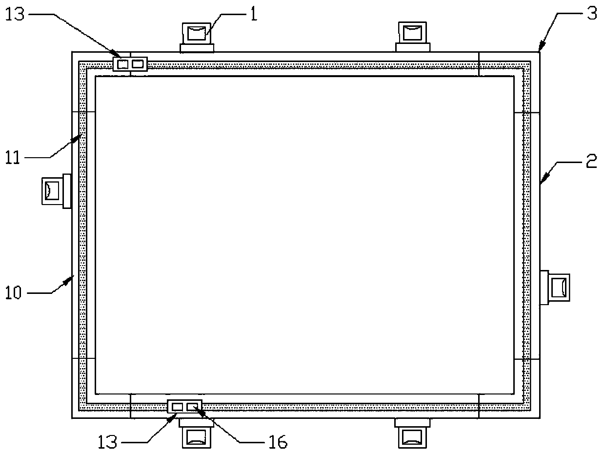
[0023] According to the different requirements for the length and width of the material, select different numbers of the first formwork 2, place the first formwork 2 on the iron workbench, place an appropriate number of connectors 13 on the first formwork 2, and take four The second template 3 is distributed in the four corners, and the first template 2 and the second template 3 are moved and adjusted to form a ring with a rectangular cross-section, and the connecting piece 13 is moved to the connection between the corresponding templates. The parts 16 are located on the two adjacent templates respectively, the stopper 16 is closed, and the abutting block 21 on the rotating shaft 15 just abuts the upper surface of the engaging mechanism 12, at this time, the connecting part 13 cannot be in the first template 2 or the second. The top of the template 3 moves to achieve the relative position fixation between the first template 2 and the second template 3; an appropriate number of magnetic clips 1 are placed on the outer sidewall of the first template 2 according to their different lengths, and the second clamp is pulled. 6. Set the second clamping plate 6 in the slot 17, and press the first clamping plate 5 against the outer side wall of the first template 2. At this time, the bump 20 is pushed to the inside of the first clamping plate 5, and the pressure plate 9 is pressed downward. , the screw 19 moves to the direction of the outer side wall of the first template 2, the magnet at the bottom of the magnetic fixing plate 4 is connected to the iron workbench, and the relative positions of the first template 2 and the second template 3 and the workbench are fixed, and the Subsequent pouring work.

PUM

no PUM

Description & Claims & Application Information

We can also present the details of the Description, Claims and Application information to help users get a comprehensive understanding of the technical details of the patent, such as background art, summary of invention, brief description of drawings, description of embodiments, and other original content. On the other hand, users can also determine the specific scope of protection of the technology through the list of claims; as well as understand the changes in the life cycle of the technology with the presentation of the patent timeline. Login to view more.

Similar technology patents

Metal die tool

InactiveCN106424566AEasy to install and removeImprove casting efficiency
Owner:TIANJIN LONGHE STEEL ALTERED METAL PROD CO LTD

Drawer backboard connecting device

InactiveCN101606787AEasy to install and removeEliminate shear force
Owner:李绍汉

Mail reminder

InactiveCN103713985AThe screws are fixed firmlyEasy to install and remove
Owner:谢虹

Classification and recommendation of technical efficacy words

  • Versatile
  • Easy to install and remove

Automobile electric control unit calibration system and method based on ASAP standard

InactiveCN101334662AVersatileResolve interface mismatch
Owner:CHONGQING UNIV OF POSTS & TELECOMM

Multi-bus automobile communication control module based on TCN

ActiveCN1889494AaccelerateVersatile
Owner:ZHUZHOU CSR TIMES ELECTRIC CO LTD

Double on-site bus interface converter

InactiveCN101345629AStrong flexibilityVersatile
Owner:WUHAN UNIV OF SCI & TECH

Enterprise collaborative office management system

InactiveCN105139181AVersatileeasy to operate
Owner:SUZHOU LANGJIETONG INTELLIGENT TECH

Clamping and sealing clamp for end of pipe

ActiveCN105179691Aeven distribution of clamping forceEasy to install and remove
Owner:HARBIN INST OF TECH

Trachea cannula tooth cushion

Owner:THE FIRST AFFILIATED HOSPITAL OF SOOCHOW UNIV
Why Eureka
Try Eureka