Supercharge Your Innovation With Domain-Expert AI Agents!

Transmission device capable of adjusting tension degree

A transmission device and tension technology, which is applied in the field of transmission devices with adjustable tension, can solve the problems of difficult adjustment of the conveyor belt, and achieve the effects of ensuring safety, prolonging service life and reducing replacement.

Inactive Publication Date: 2020-04-14
中国东方电气集团有限公司
View PDF9 Cites 2 Cited by
  • Summary
  • Abstract
  • Description
  • Claims
  • Application Information

AI Technical Summary

Problems solved by technology

[0005] In order to solve the above-mentioned technical problems, the present invention provides a transmission device with adjustable tension, which has a special mechanism for adjusting the tightness of the belt, which solves the technical problem that the conveyor belt in the transmission belt in the prior art is not easy to adjust, It can also detect whether there is any adhesion problem in the conveyed materials in time, so as to facilitate timely processing and avoid problems affecting normal production

Method used


Image

  • Transmission device capable of adjusting tension degree
  • Transmission device capable of adjusting tension degree
  • Transmission device capable of adjusting tension degree

Examples


Embodiment 1

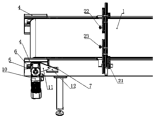
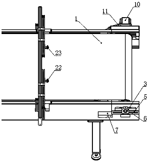
[0030] like Figure 1-2 As shown, a tension-adjustable transmission device includes a belt 1, a roller shaft 2 that drives the belt 1 to rotate, and a support unit. Both ends of the roller shaft 2 are provided with symmetrical bearing seats 3 and adjustment seats 4. , the bearing seat 3 is installed on the adjustment hole or the adjustment groove 6 of the adjustment seat 4, the adjustment direction of the adjustment hole or the adjustment groove 6 is consistent with the rotatable direction of the belt 1, the adjustment seat 4 is fixedly installed on the support unit, the bearing seat 3 can Slide along the adjustment hole or the adjustment groove 6 to drive the roller shaft 2 to move, and then achieve the purpose of adjusting the tightness of the belt 1.

Embodiment 2

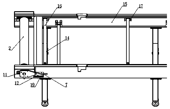
[0032] like Figure 4 As shown, on the basis of the structure of Embodiment 1, in order to better adjust the horizontal movement of the roller shaft 2, a fixed seat 7 is provided in the sliding direction of the bearing seat 3, and an adjusting threaded hole 8 and Matching adjustment screw 9, the installation direction of the adjustment screw 9 is consistent with the adjustment hole of the adjustment seat 4 or the direction of the adjustment groove 6, and one end of the adjustment screw 9 is against the bearing seat 3, and cooperates to push the bearing seat 3 along the adjustment hole of the adjustment seat 4 Or the adjustment groove 6 slips, so as to realize the movement of the roller shaft 2 and achieve the purpose of assisting in adjusting the tightness of the belt 1 .

[0033] like Figure 5 As shown, a bearing seat cover plate 4 is also provided outside the bearing seat 3 .

Embodiment 3

[0035] like Figure 3-4 As shown, on the basis of the structure of Embodiment 2, when the roller shaft 2 is used as the driving shaft, one end of the driving shaft is connected to the driving motor 10 through the bearing seat 3 . Preferably, in order to prevent the driving motor 10 from rotating during operation, a torsion arm plate 11 is also provided, one end of the torsion arm plate 11 is fixedly connected to the driving motor 10 , and the other end is slidably connected to the supporting unit or the fixing seat 7 .

[0036] Further, the fixing seat 7 is provided with a connecting plate 12 for connecting with the torsion arm plate 11 , and the connecting plate 12 is provided with a slide groove 13 which facilitates the movement of the torsion arm plate 11 . When the position of the driving shaft needs to be adjusted, the bearing seat 3 drives the torsion arm plate 11 to move, and at the same time, the torsion arm plate 11 is limited by the connecting plate 12 to prevent the...


PUM


Abstract

The invention discloses a transmission device capable of adjusting the tension degree. The device comprises a belt, a roller shaft driving the belt to rotate and a supporting unit, a bearing seat andan adjusting seat which are symmetrical in position are arranged at two ends of the roller shaft, the bearing seat is installed at the adjusting hole or the adjusting groove of the adjusting seat, theadjusting direction of the adjusting hole or the adjusting groove is consistent with the rotatable direction of the belt, the adjusting seat is fixedly installed on the supporting unit, and the bearing seat slides along the adjusting hole or the adjusting groove and drives the roller shaft to move. A double-sheet detector is also designed. The roller shaft at two ends of the belt is provided witha structure for adjusting the tightness of the belt, so the technical problem that a conveying belt in the prior art is difficult to adjust is solved, whether conveyed materials adhere or not can bedetected in time, timely treatment is facilitated, and therefore the problem that normal production is affected is avoided.

Description

technical field [0001] The invention relates to the field of conveying equipment, in particular to a conveying device with adjustable tension. Background technique [0002] As a common conveying device for assembly line operations, the conveyor belt will deform due to long-term tension during use. Once the belt is deformed, the length of the belt will increase, which will reduce the extrusion between the belt and the roller, causing slippage, which is not conducive to controlling the conveying rate of the belt, and will easily cause the conveying rhythm of the conveyed products on the belt And the processing rhythm of the processing equipment in the production line is disrupted, which is not conducive to automated production. [0003] Then, on the same transmission line (for example, during the automatic feeding process of robots or manipulators in stamping and stretching automatic lines), due to the oil film or static electricity on the surface of metal sheet parts, metal ...

Claims


Application Information

Patent Timeline
IPC IPC(8): B65G23/44
CPCB65G23/44
Inventor 陈兵石致远许辉殷庆文吴文亮李晋航董娜
Owner 中国东方电气集团有限公司
Features
  • R&D
  • Intellectual Property
  • Life Sciences
  • Materials
  • Tech Scout
  • Unparalleled Data Quality
  • Higher Quality Content
  • 60% Fewer Hallucinations
Learn More