
Detection device applied to bridge cracks

A detection device and bridge technology, which is applied in the direction of measuring devices, optical testing of flaws/defects, and material analysis through optical means, can solve the problems of bridge bearing capacity reduction, small application range, low work efficiency, etc., and reduce production and use cost, increase the scope of application, and improve work efficiency

Active Publication Date: 2020-04-14
济南工程职业技术学院
View PDF5 Cites 24 Cited by
  • Summary
  • Abstract
  • Description
  • Claims
  • Application Information

AI Technical Summary

Benefits of technology

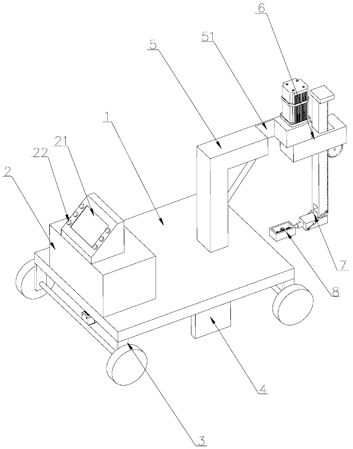
This invention relates to an apparatus used to inspect or repair damaged areas around railings such as rails alongside railway bridges. It includes two devices: a rotationally moving lift mechanism called a roller system (LF), and another test unit like a crack detector. These systems help reduce manufacture cost while increasing their effectiveness over existing methods. Additionally, there may also include various components like sensors, cameras, and light sources to enhance performance. Overall, these technical improvements make it easier and more efficient to maintain train safety and prevent damage caused by flaws found within them.

Problems solved by technology

The technical problem addressed in this patented text relates to improving the security and reliability of structures such as roads, dams, tunnels, boats, railways, etc., especially during construction activities due to their vulnerabilities towards various types of stressings like water pressure, wind force, snow loads, temperature changes, pH variations, salt concentration, hydrostatic pressures, impact forces from traffic collisions, and other environmental conditions. These stresses lead to crack formation at specific areas along these lines, causing significant economic losses and potentially dangerous consequences if they become too large overtime. Existing methods have limitations including slow response times, poor accuracy, lack of automation capabilities, high risk of injury, and limited range of applications.

Method used


Image

  • Detection device applied to bridge cracks
  • Detection device applied to bridge cracks
  • Detection device applied to bridge cracks

Examples


Embodiment Construction

[0031] Attached below Figure 1-8 , clearly and completely describe the technical solutions in the embodiments of the present invention, obviously, the described embodiments are only some of the embodiments of the present invention, not all of them. Based on the embodiments of the present invention, all other embodiments obtained by persons of ordinary skill in the art without making creative efforts belong to the protection scope of the present invention.

[0032] In describing the present invention, it should be understood that the terms "longitudinal", "transverse", "upper", "lower", "front", "rear", "left", "right", "vertical", The orientations or positional relationships indicated by "horizontal", "top", "bottom", "inner", "outer", etc. are based on the orientations or positional relationships shown in the drawings, and are only for the convenience of describing the present invention, rather than indicating or It should not be construed as limiting the invention by imply...


PUM


Abstract

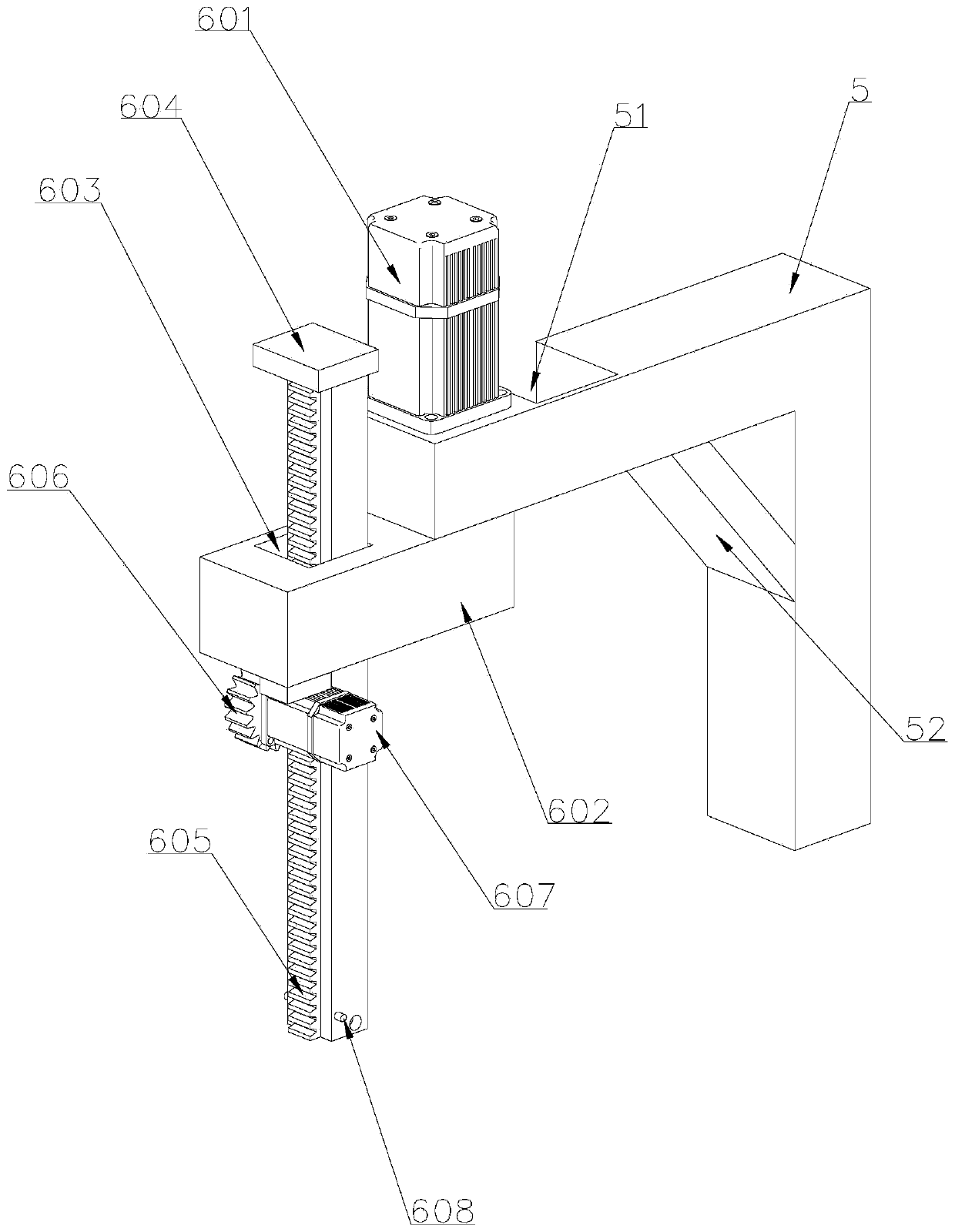
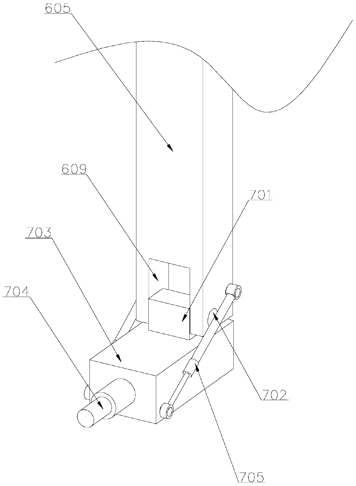
The invention discloses a detection device applied to bridge cracks. The detection device comprises a flat plate, a first flaw detection device and a second flaw detection device. The first flaw detection device is arranged at the bottom of the flat plate, a walking device is arranged at the bottom of the flat plate, and a control box is arranged on one side above the top of the flat plate. According to the invention, with the second flaw detection device, the inner side and the outer side of the side wall of the guardrail are subjected to crack detection by rotating the lifting device to change different angles; the angle of the second flaw detection device is adjusted through the angle adjusting device; crack detection can be performed on the bottom of the bridge; the inner side and theouter side of the side wall of the guardrail and the bottom of the bridge are detected through the second flaw detection device, the production and use cost is reduced, the application range of the device is widened; the first flaw detection device can move in the length direction and the width direction of the surface of the bridge, dead-corner-free detection on the surface of the bridge is realized, and the working efficiency of the device is improved.

Description


Claims


Application Information

Patent Timeline
Owner 济南工程职业技术学院
Learn More