A kind of multifunctional electric suitcase
A luggage and multi-functional technology, applied in the luggage field, can solve the problems of difficult steering, inconvenient disassembly, inconvenient motion control, etc., and achieve the effects of simple electric power assist control, labor-saving during traveling, and improved convenience.
- Summary
- Abstract
- Description
- Claims
- Application Information
AI Technical Summary
Problems solved by technology
Method used
Image
Examples
Embodiment 1
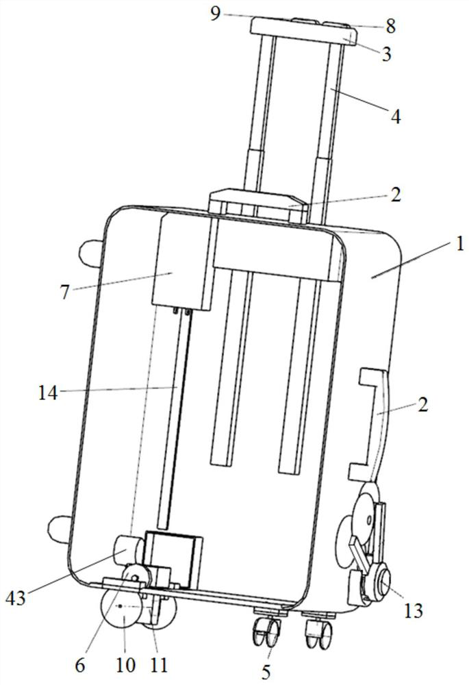
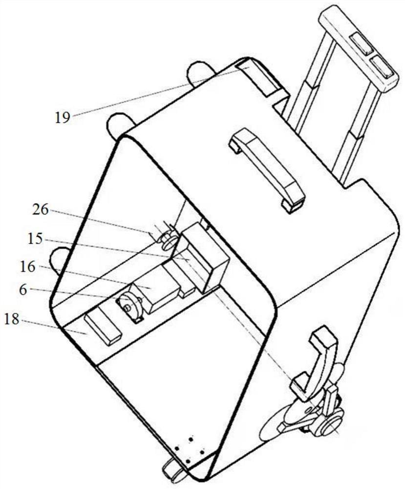
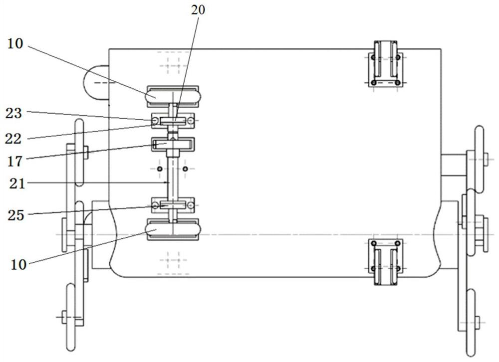
[0094] Such as figure 1 A kind of multifunctional electric suitcase shown, is put in the battery case 7 by a storage battery, can supply power for the electric suitcase, disassembles conveniently, does not affect the use by plane; There is USB interface on the battery case 7 in the case body 1. Directly charge mobile devices such as mobile phones, bid farewell to the power shortage of mobile phones when going out. The bottom plate 18 is fixedly connected with the box body 1 by screws 23, the motor 16 and the control electric box 15 are fixed on the bottom plate 18 by screws 23, the bracket 20 and the bottom of the box body 1 are fixed by screws 23, and the deep groove ball bearing 25 is installed in the bracket 20 , closed with the bearing end cover 22; The gear 17 installed on the output shaft of the motor 16 is keyed to the output shaft, and the pinion 17 installed on the transmission shaft 21 is keyed to the transmission shaft 21. The two gears mesh with each other and are...
Embodiment 2
[0096] Such as figure 1 and figure 2 A kind of multifunctional electric suitcase shown, comprises box body 1, the pull bar unit that is arranged on box body 1, the three-star wheel unit that is arranged at the bottom of both sides of box body 1, the roller unit that is arranged at box body 1 bottom, and The driving unit is arranged in the box body 1 and is connected with the roller unit through transmission.
[0097] Such as Figure 11 and Figure 12 As shown, the three-star wheel unit includes an inner shaft 27 disposed at the bottom of both sides of the box body 1, a shaft sleeve 33 slidingly sleeved on the inner shaft 27, a rotating slot 34 fixedly sleeved on the shaft sleeve 33, and a rotating slot 34 disposed on the shaft sleeve 33. The first supporting wheel 35 and the second supporting wheel 36 on the rotating card slot 34, and the third supporting wheel 37 fixedly arranged on the rotating card slot 34; wherein, the bushing 33 is a brass ring, and the third supporti...
Embodiment 3
[0126] Such as Figure 12 As shown, there is also a trigger spring sleeve between the trigger spring 28 and the inner shaft 27, which is used to reduce the direct contact between the trigger spring 28 and the inner shaft 27 and cause the wear of the trigger spring 28 or the inner shaft 27, and the trigger spring 28 is sleeved on the trigger spring On the bushing, and the trigger spring bushing is fixedly connected with the bushing 33, and the rest are the same as in Embodiment 2.
PUM
 Abstract
Description
Claims
Application Information
 - R&D
- Intellectual Property
- Life Sciences
- Materials
- Tech Scout
- Unparalleled Data Quality
- Higher Quality Content
- 60% Fewer Hallucinations
Browse by: Latest US Patents, China's latest patents, Technical Efficacy Thesaurus, Application Domain, Technology Topic, Popular Technical Reports.
© 2025 PatSnap. All rights reserved.Legal|Privacy policy|Modern Slavery Act Transparency Statement|Sitemap|About US| Contact US: help@patsnap.com


