
A multi-pin device forming device

A molding device and multi-pin technology, applied in the field of multi-pin device molding devices

Active Publication Date: 2021-05-14
HEBEI HANGUANG HEAVY IND
View PDF13 Cites 0 Cited by
  • Summary
  • Abstract
  • Description
  • Claims
  • Application Information

AI Technical Summary

Problems solved by technology

[0003] In view of this, the present invention provides a multi-pin device forming device, which solves the defects of the above-mentioned secondary bending and forming of the pins of the existing multi-pin device, and has the characteristics of stable performance, safety and high reliability

Method used


Image

  • A multi-pin device forming device
  • A multi-pin device forming device
  • A multi-pin device forming device

Examples


Embodiment Construction

[0067] The present invention will be described in detail below with reference to the accompanying drawings and examples.

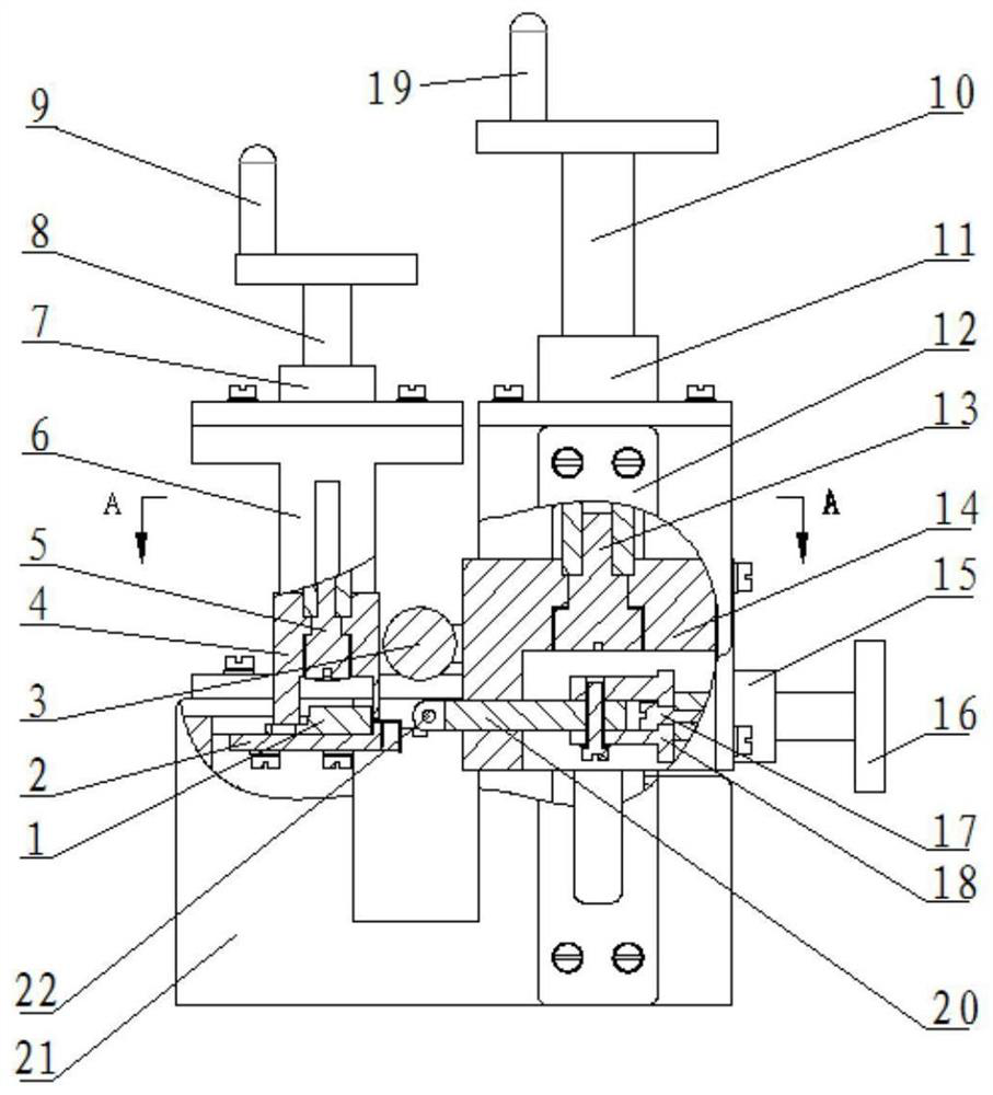
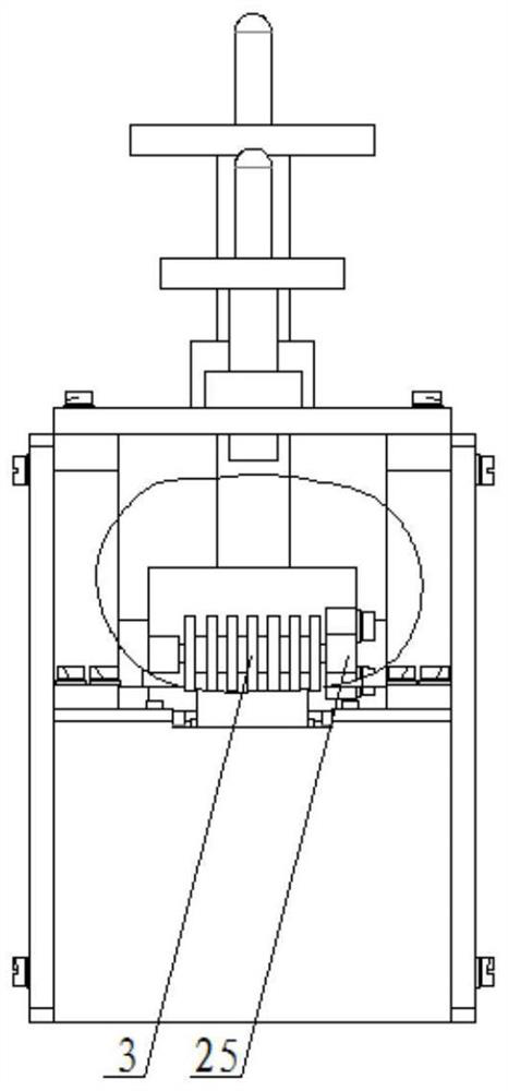
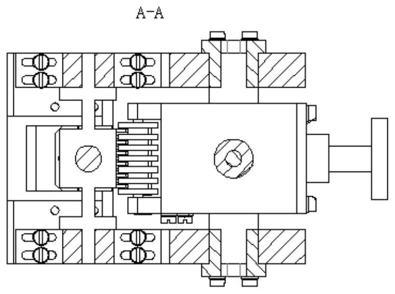
[0068] This embodiment provides a multi-pin device molding device, see the attached Figure 1-5 , including: device fixing components, device pin preliminary flattening components and device pin forming rolling components;

[0069] The device fixing assembly includes: a bracket 21, a pin forming template 2, a press-fit positioning member 4, a positioning screw shaft A5, a support plate 6, a left cover plate 7, a left screw shaft 8 and a first handle 9;

[0070] The device pin forming rolling assembly includes: pin rolling shaft 3, right screw shaft 10, right cover plate 11, guide plate 12, positioning screw shaft B13, forming frame 14, second handle 19 and rolling shaft stopper 25 ;

[0071] The device pin preliminary flattening assembly includes: side cover plate 15, horizontal screw shaft 16, positioning screw shaft C17, connecting frame 18, pin flatte...


PUM


Abstract

The invention discloses a multi-pin device forming device, which belongs to the technical field of multi-pin devices, and includes: a bracket, a pin forming template, a pin rolling shaft, a forming frame, a vertical moving component, a pin flattening frame, a lead Foot flattening shaft and horizontal moving assembly; the lead forming template is installed on the horizontal installation platform of the bracket, and the multi-pin device is placed on the lead forming template; the forming frame is installed on the bracket through the vertical moving assembly; the pin rolling shaft The two ends of the pins are respectively installed on the outer side of the forming frame; one end of the pin flattening frame is installed on the forming frame through a horizontal moving component; Stable performance, safety and high reliability.

Description

technical field [0001] The invention belongs to the technical field of multi-pin devices, and in particular relates to a molding device for multi-pin devices. Background technique [0002] Multi-pin electrical components have been widely used in military and civilian fields. The pin bending form and pin spacing of multi-pin electrical components are all standard series of the manufacturer. Due to the limitation of the design form and size of the printed board, the lead bending form and pin spacing of the standard series components of the manufacturer cannot be completely suitable for the designed printed board. It is necessary to change the shape of the component pins and change the lead Foot spacing to meet the mounting needs of printed boards. Reshaping of component pins involves many problems. For example, each pin needs to be bent and shaped one by one. Broken pins cause problems such as component scrapping. Contents of the invention [0003] In view of this, the p...

Claims


Application Information

Patent Timeline
Patent Type & Authority Patents(China)
IPC IPC(8): B21F1/00B21F1/02
CPCB21F1/004B21F1/02
Inventor 邵长春杜振华可伟周艳彬曲展张宏达
Owner HEBEI HANGUANG HEAVY IND
Learn More