Resistance welding mechanism for floor mopping robot battery

A sweeping robot and resistance welding technology, applied in resistance welding equipment, welding equipment, resistance electrode bases, etc., can solve the problems of unstable position, virtual welding, position deviation, etc., to avoid wire wear, wide applicability, cost low effect

Pending Publication Date: 2020-04-17
SUZHOU LANGKUN AUTOMATION EQUIP CO LTD
View PDF0 Cites 1 Cited by
  • Summary
  • Abstract
  • Description
  • Claims
  • Application Information

AI Technical Summary

Problems solved by technology

[0002] The battery for the sweeping robot is assembled by cylindrical batteries in series. The end of the cylindrical battery needs to be connected by connecting pieces. In order to ensure the stability of the connection, the connecting piece needs to be welded to the cylindrical battery. The efficiency of manual assembly is low, and the connecting piece is located on both sides of the cylindrical battery. , the position is unstable, and the position is prone to shift during welding. Resistance welding is used during welding. Resistance welding refers to using the resistance heat generated by the current passing through the weldment and the contact as a heat source to locally heat the piece and pressurize it at the same time. Manual hand-held welding is difficult to control the welding position and welding strength, and it is easy to cause false welding. Based on the above defects and deficiencies, it is necessary to improve the existing technology and design a resistance welding mechanism for sweeping robot batteries.

Method used


Image

  • Resistance welding mechanism for floor mopping robot battery
  • Resistance welding mechanism for floor mopping robot battery
  • Resistance welding mechanism for floor mopping robot battery

Examples


Embodiment Construction

[0022] The preferred embodiments of the present invention will be described in detail below in conjunction with the accompanying drawings, so that the advantages and features of the invention can be more easily understood by those skilled in the art, so as to define the protection scope of the present invention more clearly.

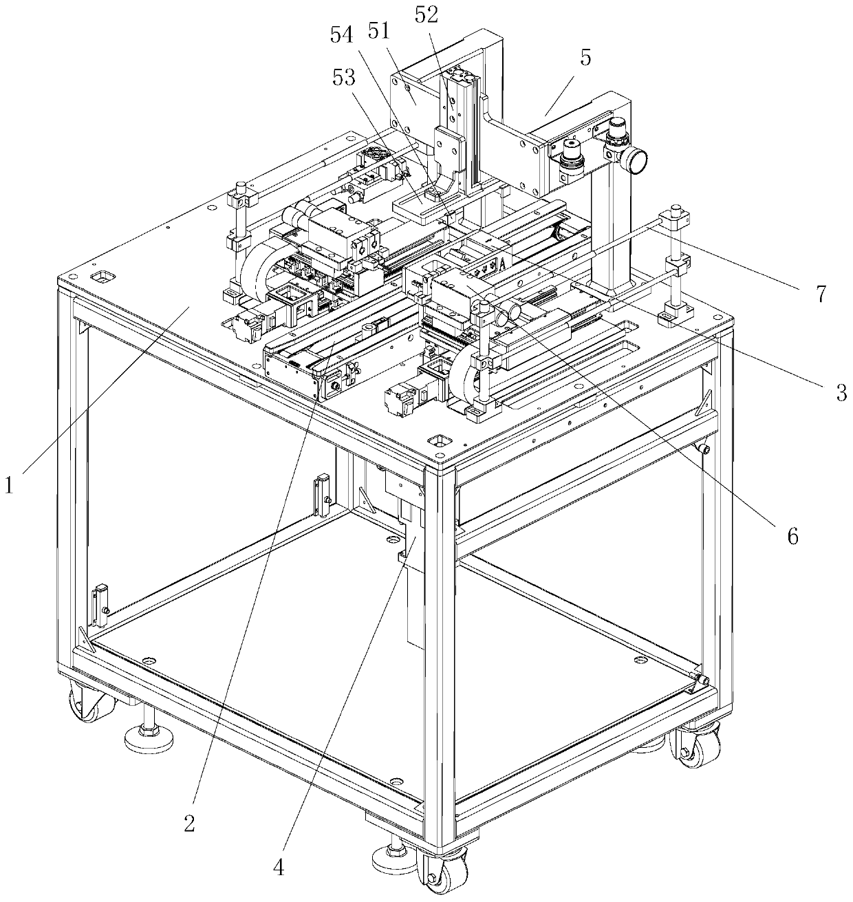
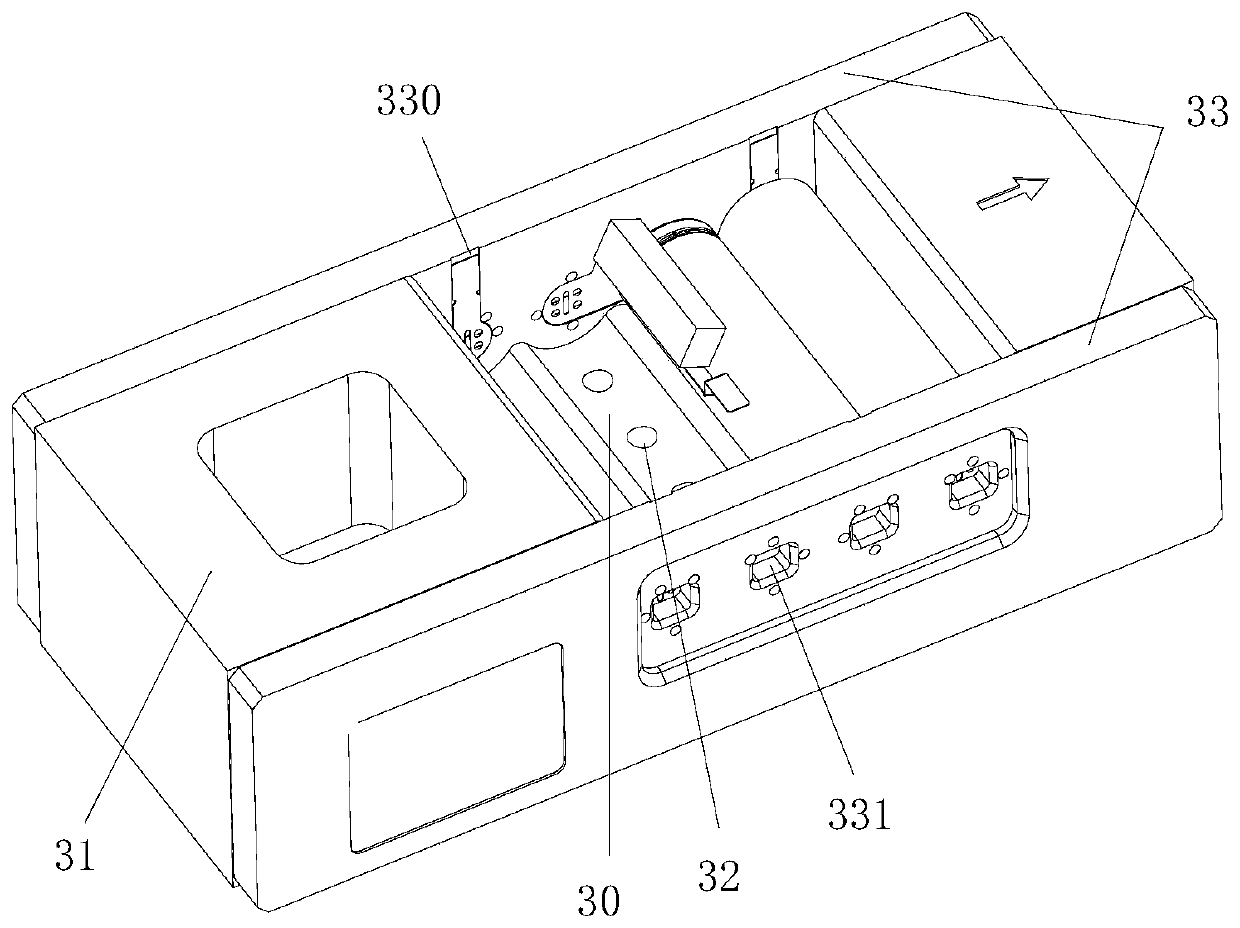
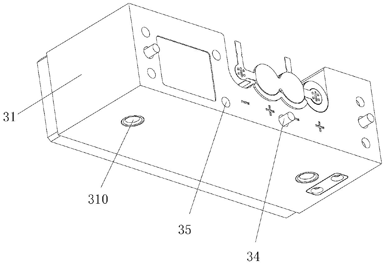
[0023] see Figure 1 to Figure 7 , the embodiment of the present invention includes:

[0024] A resistance welding mechanism for a battery of a sweeping robot, the resistance welding mechanism for a battery of a sweeping robot includes a frame 1, a conveyor 2, a resistance welding jig 3, a jacking assembly 4, a pressing assembly 5, a welding assembly 6 and a wire follower A moving assembly 7, a conveyor 2 is installed on the frame 1, a resistance welding jig 3 is conveyed on the conveyor 2, a jacking assembly 4 matching with the resistance welding jig 3 is arranged at the bottom of the frame 1, and a resistance welding jig 3 is arranged on the bottom of ...


PUM


Abstract

The invention discloses a resistance welding mechanism for a floor mopping robot battery. The resistance welding mechanism comprises a machine frame, a conveyor, a resistance welding jig, a jacking assembly, a pressing-down assembly, a welding assembly and a wire follow-up assembly. The conveyor is arranged on the machine frame and conveys the resistance welding jig. The bottom of the machine frame is provided with the jacking assembly matched with the resistance welding jig. The pressing-down assembly is arranged on the upper side of the resistance welding jig. The welding assembly and the wire follow-up assembly are arranged at the positions, on the front side and the rear side of the resistance welding jig, of the machine frame. In this way, the resistance welding mechanism is compact in structure and stable in operation, can rapidly position and install the battery and a connector and weld the battery and the connector together, and is high in work efficiency.

Description

technical field [0001] The invention relates to the technical field of electronic assembly, in particular to a resistance welding mechanism for a battery of a sweeping robot. Background technique [0002] The battery for the sweeping robot is assembled by cylindrical batteries in series. The end of the cylindrical battery needs to be connected by connecting pieces. In order to ensure the stability of the connection, the connecting piece needs to be welded to the cylindrical battery. The efficiency of manual assembly is low, and the connecting piece is located on both sides of the cylindrical battery. , the position is unstable, and the position is prone to shift during welding. Resistance welding is used during welding. Resistance welding refers to using the resistance heat generated by the current passing through the weldment and the contact as a heat source to locally heat the piece and pressurize it at the same time. The method, manual hand-held welding is difficult to co...

Claims


Application Information

Patent Timeline
IPC IPC(8): B23K11/00B23K11/31B23K11/36
CPCB23K11/00B23K11/318B23K11/36
Inventor 谢桥清陈景龙熊新郑贵军
Owner SUZHOU LANGKUN AUTOMATION EQUIP CO LTD
Why Eureka
Try Eureka