
Sliding door pulley rail assembly

A pulley assembly, sliding door technology, applied in door/window fittings, windows/doors, building components, etc., can solve the problems that the cabinet cannot be directly on the top of the wall, reduce the space utilization rate of the cabinet, and occupy the interior space of the wardrobe. , to achieve the effect of improving aesthetics, simple structure and saving space

Pending Publication Date: 2020-04-17
广东飞兽科技有限公司
View PDF0 Cites 0 Cited by
  • Summary
  • Abstract
  • Description
  • Claims
  • Application Information

AI Technical Summary

Problems solved by technology

[0002] Existing sliding doors usually use two front and rear parallel door panels. When the two door panels are closed, the two door panels are in an overlapping state, which reduces the space utilization of the cabinet; however, the door panels and the switch door assembly occupy the inner space of the wardrobe
Or the form of hanging rails directly on the top of the cabinet body, but the cabinet body cannot directly reach the top of the wall, which affects the appearance

Method used


Image

  • Sliding door pulley rail assembly
  • Sliding door pulley rail assembly
  • Sliding door pulley rail assembly

Examples


Embodiment Construction

[0040] The embodiments of the present invention are described in detail below. Examples of the embodiments are shown in the accompanying drawings, wherein the same or similar reference numerals represent the same or similar elements or elements with the same or similar functions. The embodiments described below with reference to the drawings are exemplary, and are only used to explain the present invention, but should not be understood as limiting the present invention.

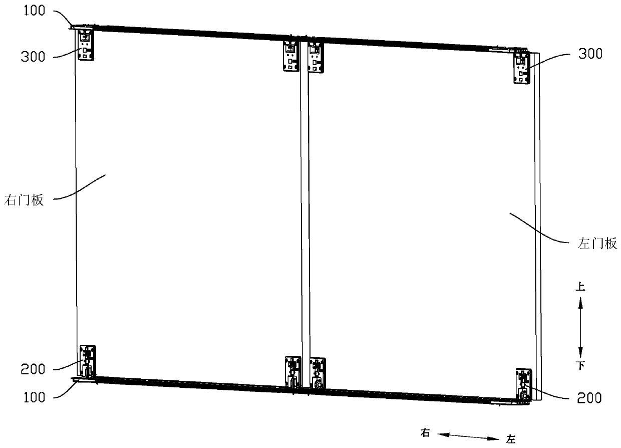
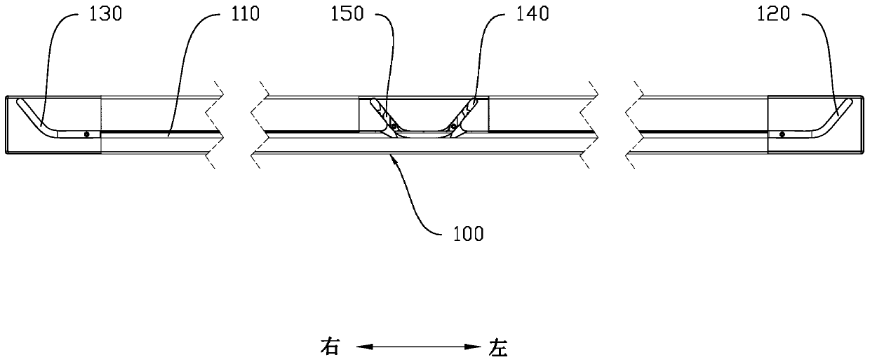
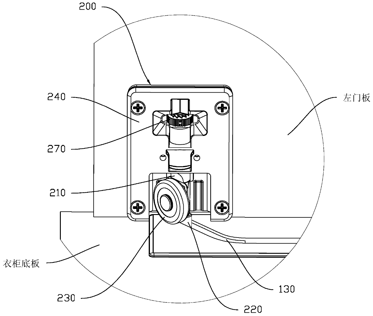
[0041] Reference figure 1 , figure 2 As shown, a sliding door pulley track assembly includes two slide grooves 100, four pulley components 200, and four guide column components 300; the two slide grooves 100 are installed on the top and bottom of the wardrobe symmetrically, respectively, for To realize the sliding door opening and closing of the left and right door panels, the two sliding grooves 100 each include a straight sliding groove 110, and the left and right ends of the straight sliding groove 110 are re...


PUM


Abstract

The invention discloses a sliding door pulley rail assembly. The sliding door pulley rail assembly comprises two sliding grooves, four pulley assemblies and four guide column assemblies. A left door plate moves in sliding grooves in a wardrobe top plate and a wardrobe bottom plate through the two pulley assemblies and the two guide column assemblies. When the left door plate simultaneously moves to straight sliding grooves from the head ends of two first left arc sliding grooves and the head ends of two second left arc sliding grooves and then moves to the right, the leftward door opening action is achieved, and the door closing action is achieved through reverse moving; a right door plate moves in the sliding grooves in the wardrobe top plate and the wardrobe bottom plate through the twopulley assemblies and the two guide column assemblies, when the right door plate simultaneously moves to straight sliding grooves from the head ends of two first right arc sliding grooves and the headends of two second right arc sliding grooves and then moves to the left, the rightward door opening action is achieved, and the door closing action is achieved through reverse moving; and when the door is closed, the left door plate and the right door plate are flush with each other. The sliding door pulley rail assembly has the beneficial effects that the structure is simple, the mounting is convenient, the space inside a wardrobe is saved during mounting, and the overall aesthetic degree of the wardrobe is increased.

Description

Technical field [0001] The invention relates to the field of sliding doors, in particular to a sliding door pulley track assembly. Background technique [0002] Existing sliding doors usually use two parallel door panels. When the two door panels are closed, the two door panels are in an overlapping state, which reduces the cabinet space utilization rate; however, the door panels and the switch door assembly occupy the internal space of the wardrobe. Or you can add rails directly on the top of the cabinet, but the cabinet cannot be directly on the wall, which affects the appearance. Summary of the invention [0003] The present invention aims to solve at least one of the technical problems existing in the prior art. For this reason, the present invention proposes a sliding door pulley track assembly, which can realize that two door panels are flush with each other when they are closed. And there is no need to install rails on the top of the cabinet; it can also be used on small ...

Claims


Application Information

Patent Timeline
IPC IPC(8): E06B3/46E06B5/00E05D13/00E05D15/06A47B61/00
CPCA47B61/00E05D13/00E05D15/0647E05D15/0652E05D15/0682E05D15/0686E06B3/4636E06B5/006
Inventor 冯秋波任恒
Owner 广东飞兽科技有限公司
Learn More