Pump body assembly and slide vane compressor with pump body assembly

A component and pump body technology, applied in the field of compressors, can solve the problems affecting the normal operation of the sliding vane compressor and the low strength of the flange structure, and achieve the effect of improving the operation reliability, prolonging the service life and ensuring the normal use.

Pending Publication Date: 2020-04-17
GREE ELECTRIC APPLIANCES INC
View PDF0 Cites 6 Cited by
  • Summary
  • Abstract
  • Description
  • Claims
  • Application Information

AI Technical Summary

Problems solved by technology

[0004] The main purpose of the present invention is to provide a pump body assembly and a vane compressor with it, so as to solve the problem in the prior art that the structural strength of the flange is low and affect the normal operation of the vane compressor

Method used


Image

  • Pump body assembly and slide vane compressor with pump body assembly
  • Pump body assembly and slide vane compressor with pump body assembly
  • Pump body assembly and slide vane compressor with pump body assembly

Examples


Embodiment 1

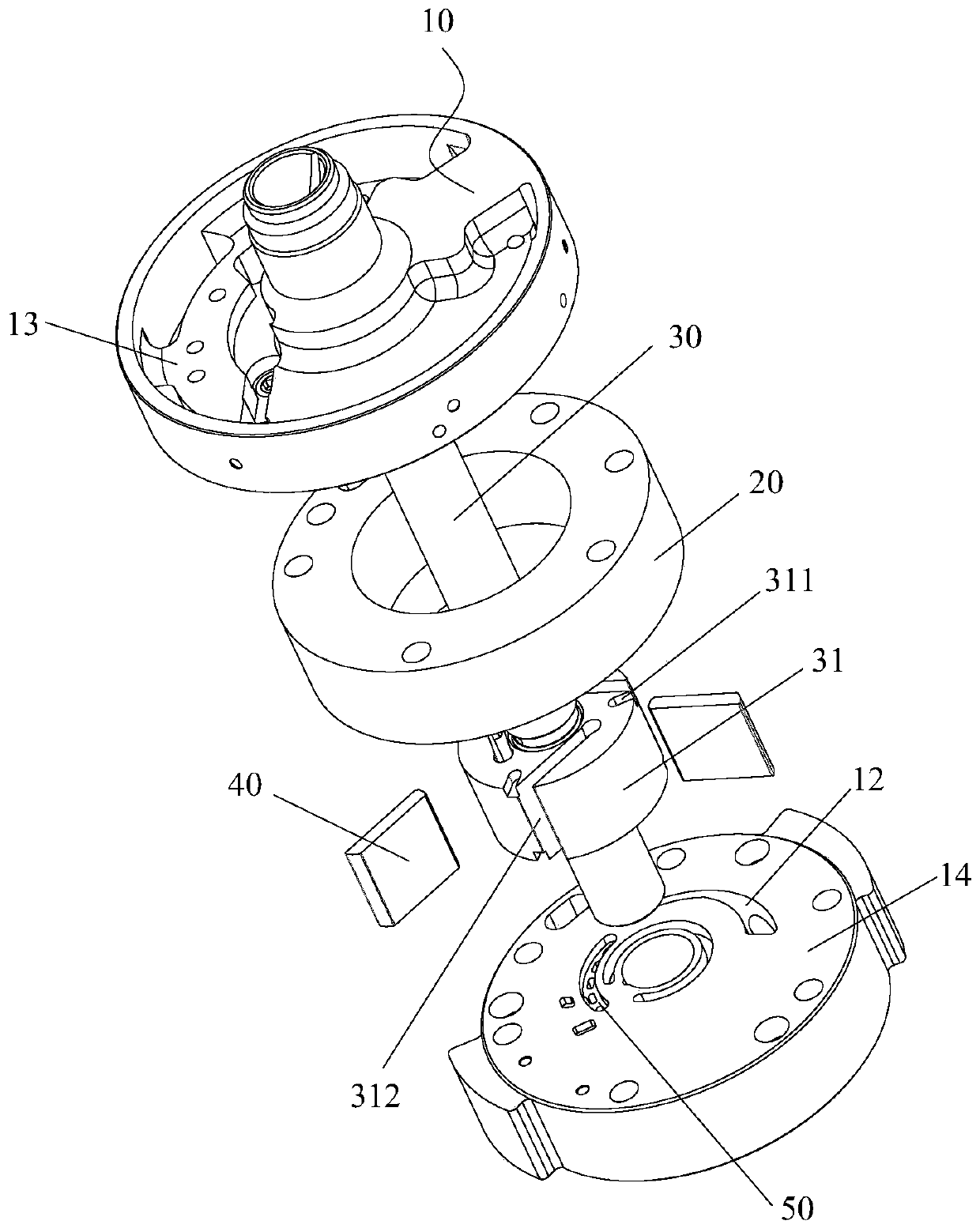
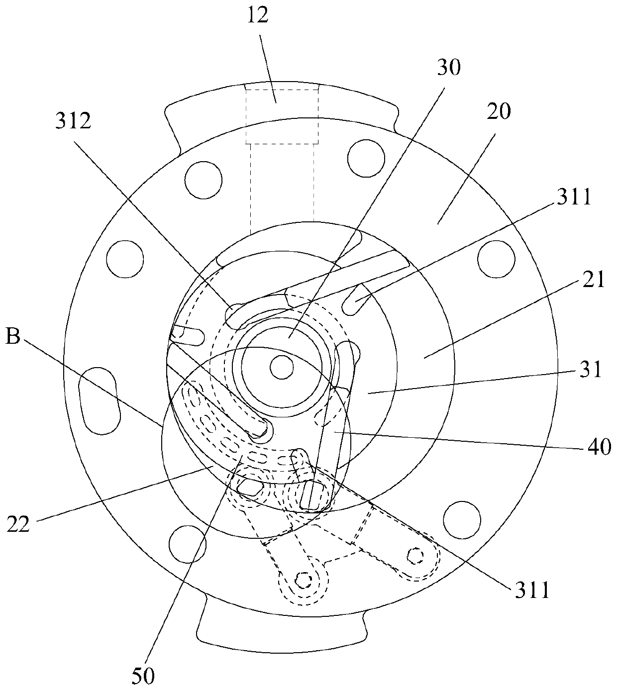
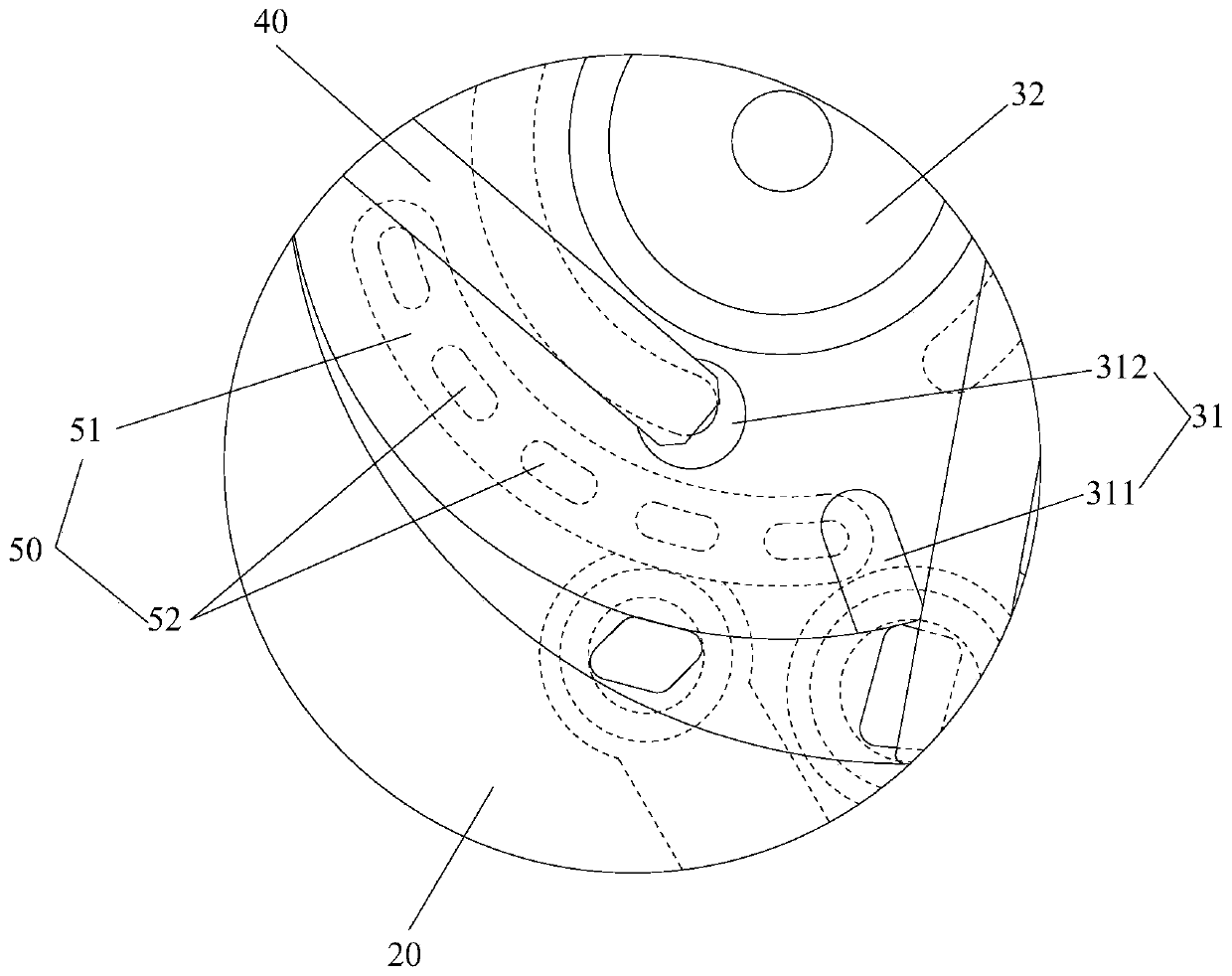
[0042] like figure 1 and figure 2 As shown, the pump body assembly includes a flange 10, a cylinder 20, a rotating shaft 30 and three slides 40, the slides 40 are slidably arranged on the rotor part 31 of the rotating shaft 30, and the rotor part 31 is located in the cylinder 20, the pump body assembly An exhaust structure 50 is also included. The exhaust structure 50 is arranged on the flange 10. The exhaust structure 50 includes a diversion groove 51 and an exhaust hole 52 communicating with the diversion groove 51. The exhaust hole 52 extends from the groove bottom of the diversion groove 51 to the flange 10. on the end face. Wherein, the rotor part 31 has an exhaust groove 311. During the rotation of the rotating shaft 30, the gas in the compression chamber 21 of the cylinder 20 enters the guide groove 51 through the exhaust groove 311, so as to enter the exhaust hole through the guide groove 51. 52, and through the exhaust hole 52 to the outside of the pump body assem...

Embodiment 2

[0076] The difference between the pump body assembly in the second embodiment and the first embodiment is that the structure of the exhaust structure 50 is different.

[0077] like Figure 12 and Figure 13 As shown, the exhaust structure 50 also includes a guide hole 53 . Wherein, the diversion hole 53 communicates with the diversion groove 51 , and the diversion hole 53 extends to two opposite end surfaces of the flange 10 . Specifically, during the operation of the pump body assembly, the rotating shaft 30 rotates so that the rotor portion 31 and the sliding plate 40 compress the gas in the cylinder 20, and the gas in the compression chamber 21 of the cylinder 20 can pass through the exhaust groove. 311 enters the diversion groove 51 to enter the exhaust hole 52 through the diversion groove 51, and is discharged to the outside of the pump body assembly through the exhaust hole 52, or directly enters the diversion hole 53, and is discharged through the diversion hole 53 to...


PUM


Abstract

The invention provides a pump body assembly and a slide vane compressor with the pump body assembly. The pump body assembly comprises a flange, an air cylinder, a spindle and multiple slide vanes, wherein the slide vanes are slidably arranged on a rotor part of the spindle; and the rotor part is located in the air cylinder. The pump body assembly further comprises an exhaust structure arranged onthe flange, wherein the exhaust structure comprises a diversion trench and an exhaust hole communicating with the diversion trench; the exhaust hole extends onto the end surface of the flange from thebottom of the diversion trench; the rotor part is provided with an exhaust trough; in the rotation process of the spindle, gas located in a compression cavity of the air cylinder enters the diversiontrench through the exhaust trough, enters the exhaust hole through the diversion trench, and is exhausted to the outside of the pump body assembly through the exhaust hole. The pump body assembly andthe slide vane compressor with the pump body assembly provided by the invention effectively solve the problem that the structural strength of a flange in the prior art is lower so as to affect the normal operation of the slide vane compressor.

Description

technical field [0001] The invention relates to the technical field of compressors, in particular to a pump body assembly and a sliding vane compressor having the same. Background technique [0002] At present, in order to solve the problems of high exhaust speed and large exhaust resistance due to the small exhaust area of ​​the vane compressor in the prior art, an annular hole is arranged on the flange of the vane compressor for exhaust. gas. [0003] However, the above-mentioned settings lead to insufficient strength of the journal of the flange, which easily causes deformation at the position of the annular hole, which affects the coaxiality of the main shaft, aggravates the deflection deformation, increases the mechanical power consumption of the sliding vane compressor, and reduces the capacity of the sliding vane compressor. The overall performance of the compressor even affects the reliability and service life of the vane compressor. Contents of the invention [...

Claims


Application Information

Patent Timeline
Patent Type & Authority Applications(China)
IPC IPC(8): F04C29/12F04C18/344
CPCF04C18/3441F04C29/12
Inventor 胡余生魏会军徐嘉吴飞万鹏凯罗发游任丽萍邹鹏
Owner GREE ELECTRIC APPLIANCES INC
Why Eureka
Try Eureka