
Roller bearing retainer

A technology of roller bearings and cages, which is applied to bearing components, shafts and bearings, mechanical equipment, etc., can solve problems affecting balance, bearing life, and cage wear, and achieve reduced resistance, stable operation, and small impact loads Effect

Active Publication Date: 2020-04-17
LUOYANG BEARING RES INST CO LTD
View PDF7 Cites 7 Cited by
  • Summary
  • Abstract
  • Description
  • Claims
  • Application Information

AI Technical Summary

Problems solved by technology

[0003] The technical problem to be solved by the present invention is to provide a roller bearing cage, which solves the existing problems of the existing roller bearing cage, such as affecting the balance during high-speed operation, insufficient lubricating oil on the contact surface, causing serious wear of the cage, and affecting the service life of the bearing.

Method used


Image

  • Roller bearing retainer
  • Roller bearing retainer
  • Roller bearing retainer

Examples


Embodiment Construction

[0018] The specific implementation manners of the present invention will be described and described in detail below in conjunction with the accompanying drawings.

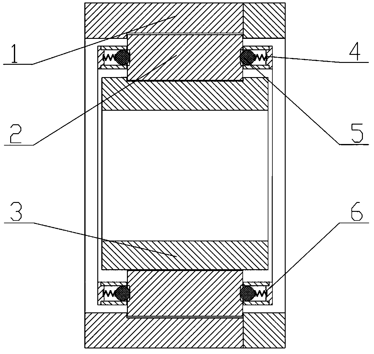
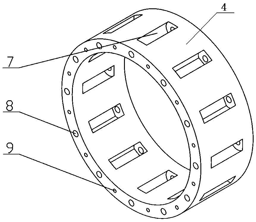
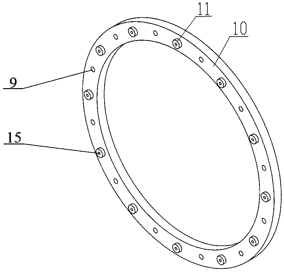
[0019] As shown in the figure, a roller bearing cage is characterized in that it includes a cage body 4 and an annular cage baffle 10 connected to both sides of the cage body 4 and matching the shape of the cage body 4 A through hole 8 communicating with the pocket hole 7 is provided on both sides of the end surface of the cage body 4 corresponding to each pocket hole 7, and a convex hole 8 that is matched with each through hole 8 is provided on the corresponding position of the retainer baffle plate 10. Out of the column 11, the cage main body 4 and the cage baffle 10 are connected through the protruding column 11 and the through hole 8, and the through holes 8 on both sides of the bearing roller 2 are respectively provided with supporting balls from the bearing roller 2 to the outside. 5 and spring 6, support bal...


PUM


Abstract

The invention discloses a roller bearing retainer, and relates to the technical field of roller bearings. The roller bearing retainer comprises a retainer main body as well as circular ring shaped retainer baffle plates which are connected to the two sides of the retainer main body, and are matched with the shape of the retainer main body, wherein through holes which communicate with pocket holesare formed in positions, corresponding to the pocket holes, in two side end surfaces of the retainer main body; a bulged column which is matched with each through hole is arranged on the correspondingposition of each retainer baffle plate; the retainer main body and the retainer baffle plates are connected through the bulged columns and the through holes; supporting balls and springs are outwardssequentially arranged in the through holes in the two sides of a roller bearing from the roller bearing; and the supporting balls abut against in concave surfaces at the two ends of the roller bearing. The roller bearing retainer has the beneficial effects that a roller bearing adopting the structure of the retainer is simple in structure, is small in impact load, supplements lubricating oil conveniently, and has a lubricating oil self-supplementing function in an operation process.

Description

technical field [0001] The invention belongs to the technical field of roller bearings, and in particular relates to a roller bearing cage. Background technique [0002] Roller bearings are one of the more commonly used components in large production equipment. It mainly includes outer ring, inner ring, roller and cage. The cover and seat of the commonly used copper alloy solid cage are connected by rivets, the verticality of the rivet holes is difficult to guarantee, and the balance will be affected during high-speed operation. During the operation of the roller bearing, the pocket and the roller are in surface contact, the gap is small, the collision force between the roller and the cage is large, and the contact surface lubricating oil is insufficient, which will cause serious wear of the cage, increase the temperature of the bearing, and cause vibration And noise, causing the bearing life to be seriously affected. Those skilled in the art have been looking for feasibl...

Claims


Application Information

Patent Timeline
Patent Type & Authority Applications(China)
IPC IPC(8): F16C33/46F16C33/66
CPCF16C33/46F16C33/6622F16C33/6629F16C33/6659F16C33/6681
Inventor 郑昊天李庆林尹延经李燕春铁晓艳魏銮李东亚
Owner LUOYANG BEARING RES INST CO LTD
Learn More