
A structure for suppressing redundant degrees of freedom of planetary row floating parts

A technology of floating parts and degrees of freedom, which is applied in the direction of transmission parts, belts/chains/gears, mechanical equipment, etc., can solve problems such as braking process collapse, meshing instability, and gear tooth damage, so as to reduce interference sources and suppress The effect of excess degrees of freedom

Active Publication Date: 2021-03-19
CHINA NORTH VEHICLE RES INST
View PDF7 Cites 0 Cited by
  • Summary
  • Abstract
  • Description
  • Claims
  • Application Information

AI Technical Summary

Problems solved by technology

[0002] Since there is often a floating ring gear design in planetary gearboxes, the ring gear is in a fully floating state during the meshing process without limiting any degrees of freedom; during braking, the meshing between the floating ring gear and the planetary gear is unstable , although the planetary gear and the sun gear are constrained, the floating of the floating ring gear and the friction plate on it is an important source of many unstable factors. Due to the structural design of the full floating ring gear, too many degrees of freedom are released, although Finally, it can rotate around the axial direction, but it is easy to be disturbed in other directions of the axial degree of freedom, resulting in instability in the friction plate bonding process; this instability is very easy to cause friction plate burns and cracks in the tooth root when the working conditions are bad And other phenomena, which will cause the collapse of the braking process, resulting in the breakage of the friction piece teeth, the gear teeth and even the damage of the gear teeth on the ring gear.

Method used


Image

  • A structure for suppressing redundant degrees of freedom of planetary row floating parts

Examples


Embodiment Construction

[0011] The present invention will be described in further detail below in conjunction with the accompanying drawings.

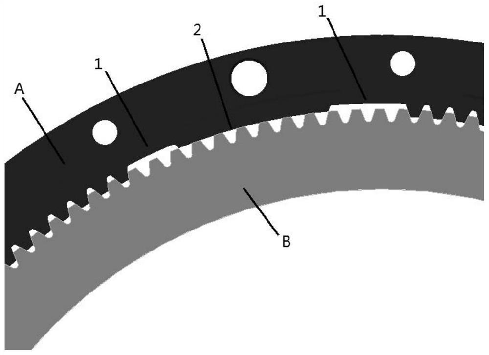
[0012] Such as figure 1 As shown, the present invention provides a new structure that suppresses the redundant degrees of freedom of the floating parts of the planetary row. A plurality of gear teeth on the outer drum of the gearbox brake drum A are processed into an arc 2, and this section of the arc is in contact with the friction plate (steel Sheet) B gear teeth form a clearance fit, and multiple gear teeth on both sides of the arc on the outer drum of the transmission brake drum A are milled off corresponding multiple gear teeth according to the inner diameter of the inner gear addendum circle of the transmission brake drum. Groove; the friction plate (steel plate) B and the outer drum of the gearbox brake drum A form a cylindrical pair in the axial direction (that is, the normal line of the paper surface), and the two can move along the axial direction. ...


PUM


Abstract

The invention belongs to the field of mechanical transmission, and relates to a novel structure for inhibiting redundant freedom degree of a planet row floating piece. A plurality of gear teeth on anouter drum of a gearbox brake drum A in the structure are machined into a circular arc, the circular arc is in clearance fit with the gear teeth of a friction plate B, and the plurality of gear teethon both sides of the circular arc on the outer drum of the gearbox brake drum A are milled out according to the inner diameter of an addendum circle of the gear teeth in the gearbox brake drum to formgrooves; and a cylindrical pair is formed between the friction plate B and the outer drum of the gearbox brake drum A in the axial direction. The novel structure has the advantages that the redundantfreedom degree in the design of the planet row floating gear ring is inhibited, interference sources of unstable factors in the combining and separating process of the friction plate are reduced, andthe risk that the friction plate, the planet row floating gear ring, even a whole planet gearbox bearing and the like are damaged and lose efficacy due to burning of the friction plate is greatly reduced; and the reliability of the friction plate, the planet row floating piece and even the whole planet transmission equipment is improved.

Description

technical field [0001] The invention belongs to the field of mechanical transmission and relates to a new structure for suppressing redundant degrees of freedom of planetary row floating parts. Background technique [0002] Since there is often a floating ring gear design in planetary gearboxes, the ring gear is in a fully floating state during the meshing process without limiting any degrees of freedom; during braking, the meshing between the floating ring gear and the planetary gear is unstable , although the planetary gear and the sun gear are constrained, the floating of the floating ring gear and the friction plate on it is an important source of many unstable factors. Due to the structural design of the full floating ring gear, too many degrees of freedom are released, although Finally, it can rotate around the axial direction, but it is easy to be disturbed in other directions of the axial degree of freedom, resulting in instability in the friction plate bonding proce...

Claims


Application Information

Patent Timeline
Patent Type & Authority Patents(China)
IPC IPC(8): F16H57/10F16H57/023
CPCF16H57/023F16H57/10
Inventor 尹华兵邢庆坤张静唐沛张鹤贾爽
Owner CHINA NORTH VEHICLE RES INST
Learn More