
Coupling sleeve assembly, double-shaft type servo motor and automatic equipment

A technology of servo motors and coupling sleeves, which is applied to mechanical equipment, couplings, electric components, etc., and can solve problems such as front and rear shaft wear, poor coaxiality of front and rear shafts, and inability to fully fit tightly

Inactive Publication Date: 2021-04-27
GREE ELECTRIC APPLIANCES INC
View PDF8 Cites 0 Cited by
  • Summary
  • Abstract
  • Description
  • Claims
  • Application Information

AI Technical Summary

Problems solved by technology

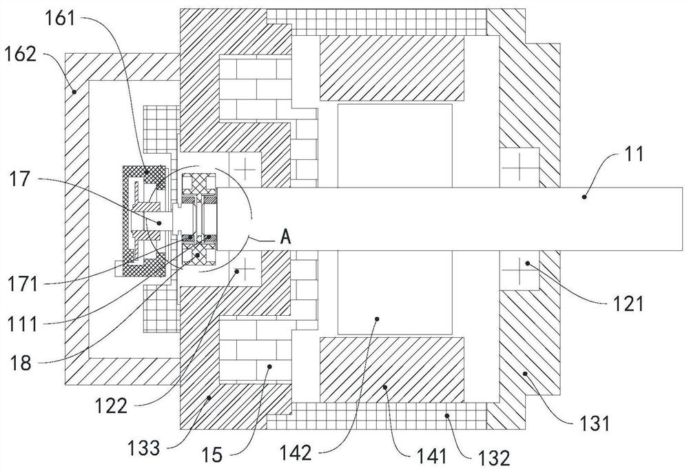
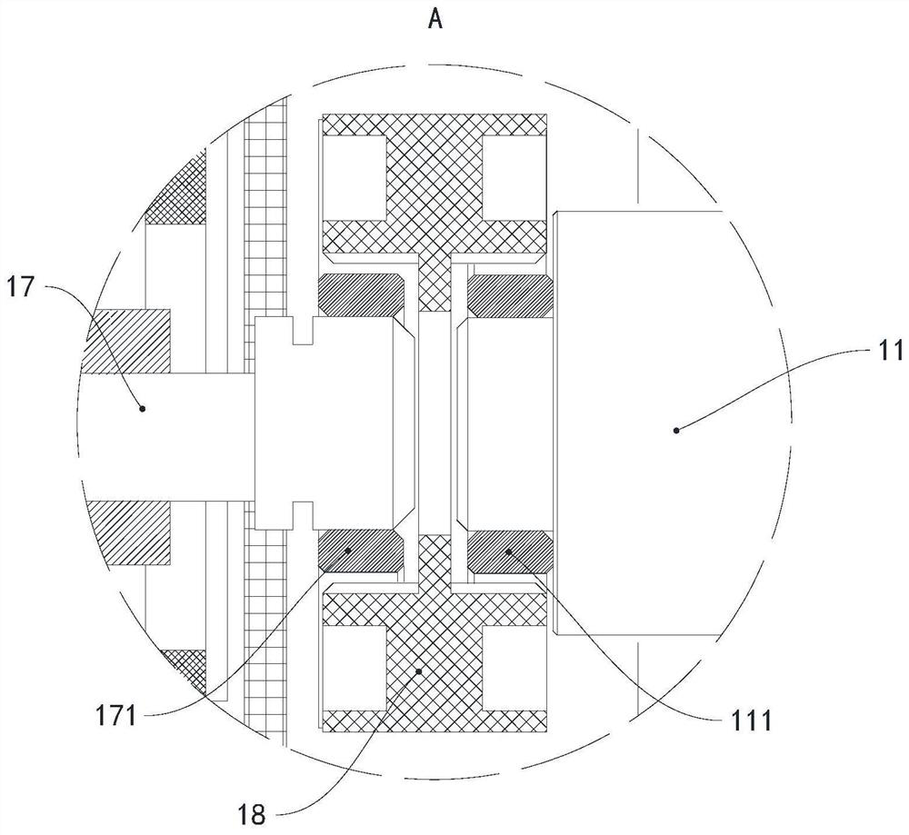
[0004] The advantage of this structure is to reduce the temperature rise of the encoder end. However, in the actual installation process, there are errors in the process of each part of the motor, and the final assembly of the plastic connection block 18 can only be seen with the eyes, and the axis of the motor front shaft 11 cannot be guaranteed. The center is consistent with the axis of the motor rear axle 17
There is a certain gap in the fit and assembly of this connecting block, which cannot be completely tightly matched, resulting in a further increase in the coaxiality error. Due to the process, the coaxiality of the front and rear axles is poor, which will generate torsion.
After the motor has been running for a long time, the front and rear axles are worn due to torque, which affects the life of the motor

Method used


Image

  • Coupling sleeve assembly, double-shaft type servo motor and automatic equipment
  • Coupling sleeve assembly, double-shaft type servo motor and automatic equipment
  • Coupling sleeve assembly, double-shaft type servo motor and automatic equipment

Examples


Embodiment Construction

[0035] The first embodiment of the shaft coupling sleeve assembly and the double-shaft servo motor

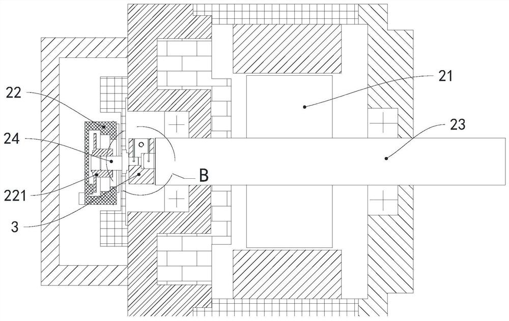
[0036] see Figure 3 to Figure 5 , The biaxial servo motor includes a rotor 21, an encoder 22, a motor front shaft 23, a motor rear shaft 24 and a coupling sleeve assembly. The motor front shaft 23 is fixedly connected to the rotor 21, the motor rear shaft 24 is fixedly connected to the code disc 221 of the encoder 22, the motor front shaft 23 is connected to the motor rear shaft 24 through a coupling sleeve assembly, and the coupling sleeve assembly includes a shaft coupling Sleeve 3 and fixing piece 4 ( Figure 6 Shown), the coupling sleeve 3 is a plastic part, and the fixing part 4 is a screw.

[0037] The shaft coupling sleeve 3 is provided with a shaft sleeve hole 31 penetrating in the axial direction, and the motor front shaft 23 and the motor rear shaft 24 respectively extend into the shaft sleeve hole 31 from both ends of the shaft coupling sleeve 3 .

[0038] The pe...


PUM


Abstract

The invention provides a coupling sleeve assembly, a double-shaft type servo motor and automatic equipment. The coupling sleeve assembly comprises a coupling sleeve and a fixing piece, wherein the coupling sleeve is provided with a shaft sleeve hole in a penetrating mode in the axial direction; a first clamping part, a second clamping part and an air outlet groove set are arranged on the circumferential wall of the coupling sleeve, the first clamping part and the second clamping part are arranged in the circumferential direction of the coupling sleeve, a first fixing hole is formed in the first clamping part, a second fixing hole is formed in the second clamping part, and the fixing piece sequentially penetrates through the first fixing hole and the second fixing hole; the first clamping part and the second clamping part are stressed to move towards the shaft sleeve hole, and the air outlet groove set communicates with the shaft sleeve hole. According to the coupling sleeve assembly, the coaxiality error between the front shaft and the rear shaft can be reduced, so abrasion of the motor shaft is reduced, and installation is convenient.

Description

technical field [0001] The invention relates to the technical field of motors, in particular to a shaft coupling sleeve assembly, a double-shaft servo motor and automation equipment. Background technique [0002] see figure 1 , split servo motor generally consists of motor front shaft 11, main bearing 121, front end cover 131, middle end cover 132, stator 141, rotor 142, brake 15, rear end cover 133, auxiliary bearing 122, encoder 161, encoder cover 162. Composed of components such as the motor rear shaft 17, it is an electromagnetic device that uses a magnetic field as a medium to convert mechanical energy and electrical energy. It is currently widely used in various fields such as industrial robots and numerical control machine tools. [0003] Such as figure 2 As shown, the connecting block assembly inside the split motor includes a front axle end connecting block 111 , a plastic connecting block 18 and a rear axle end connecting block 171 . Positioning protrusions are...

Claims


Application Information

Patent Timeline
Patent Type & Authority Applications(China)
IPC IPC(8): H02K7/00H02K7/08F16D1/08
CPCH02K7/003H02K7/08F16D1/08
Inventor 孙曦王大号周丹
Owner GREE ELECTRIC APPLIANCES INC
Learn More