
Air-blowing micro-cable and manufacturing method

A manufacturing method and technology for micro-cables, which are applied to instruments, fiber mechanical structures, optics, etc., can solve problems such as unfavorable air-blowing performance of micro-cables, low production efficiency of air-blown micro-cables, and affecting the regularity of stranding patterns of optical fiber units. , to achieve the effect of improving air blowing performance, improving production efficiency and reducing circulation time

Active Publication Date: 2020-04-17
JIANGSU ZHONGTIAN TECH CO LTD
View PDF8 Cites 1 Cited by
  • Summary
  • Abstract
  • Description
  • Claims
  • Application Information

AI Technical Summary

Problems solved by technology

Since the cabling and sheathing processes cannot be combined into one during the production process, the production efficiency of air-blown microcables is low
Moreover, the conventional layer-twisted air-blown microcable structure has a yarn binding between the optical fiber unit and the sheath, and the thickness of the yarn binding affects the regularity of the stranding pattern of the optical fiber unit on the surface of the sheath, which is not conducive to the air-blowing performance of the microcable. promotion

Method used

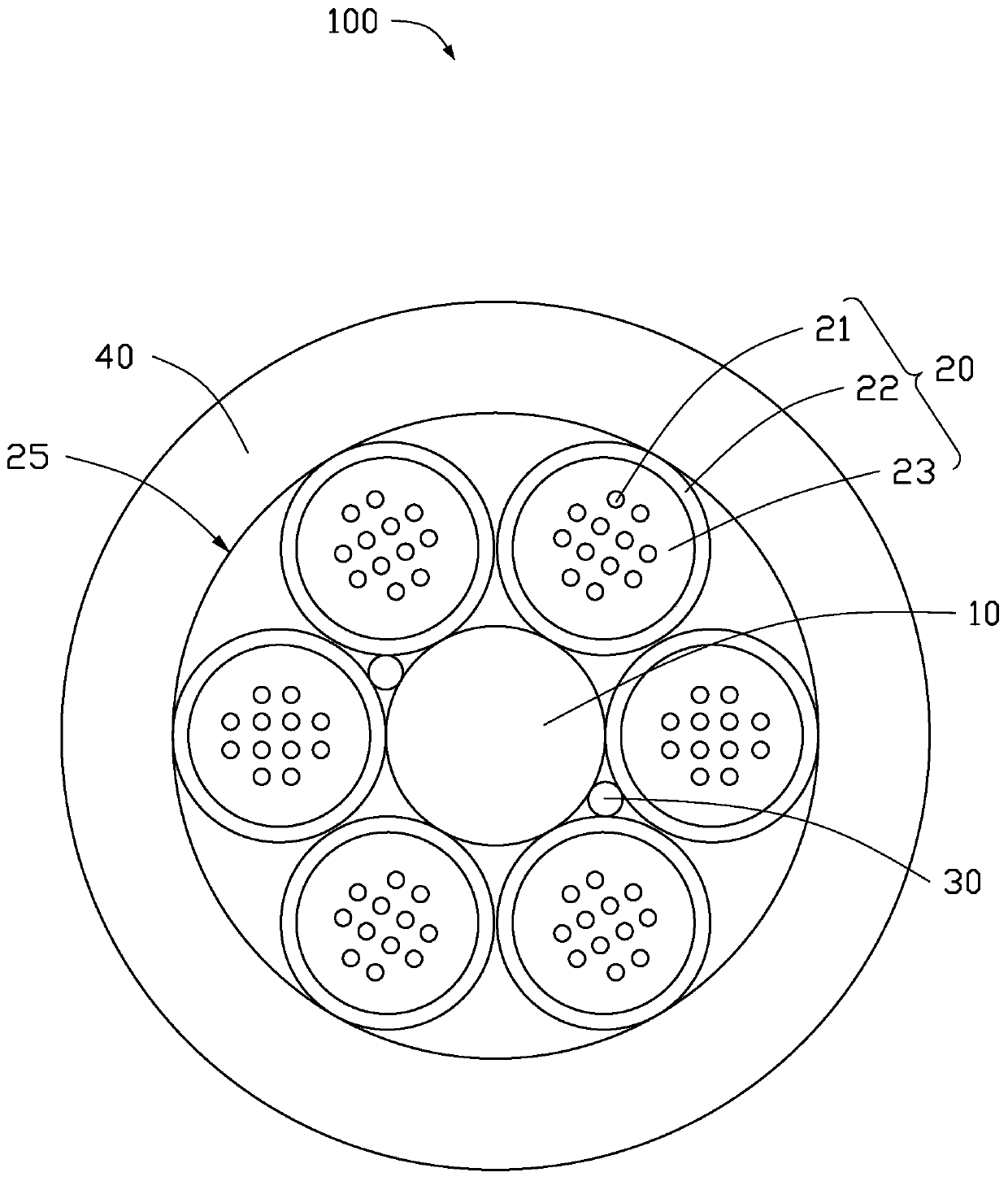
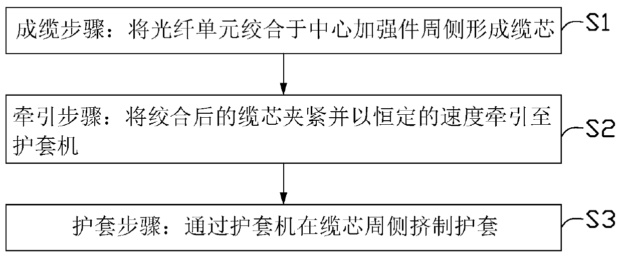

Image

  • Air-blowing micro-cable and manufacturing method
  • Air-blowing micro-cable and manufacturing method

Examples


Embodiment Construction

[0024] In order to more clearly understand the above objects, features and advantages of the embodiments of the present invention, the present invention will be described in detail below in conjunction with the accompanying drawings and specific embodiments. It should be noted that, in the case of no conflict, the features in the embodiments of the present application may be combined with each other.

[0025] In the following description, a lot of specific details are set forth in order to fully understand the embodiments of the present invention, and the described implementations are part of the implementations of the present invention, but not all of the implementations. Based on the implementation manners in the present invention, all other implementation manners obtained by persons of ordinary skill in the art without making creative efforts belong to the protection scope of the embodiments of the present invention.

[0026] Unless defined otherwise, all technical and scie...


PUM


Abstract

The present invention relates to an air-blowing micro-cable and a manufacturing method. The method comprises: a cabling step of twisting an optical fiber unit around a central reinforcement to form acable core; a traction step of clamping the stranded cable core and pulling the stranded cable core to a sheathing machine at a constant speed; and a sheathing step of performing sheathing extrusion on the peripheral side of the cable core through the sheathing machine. The cable core in the traction step is clamped by traction equipment and is dragged to the sheathing machine at a constant speed.The air-blowing micro-cable comprises a central reinforcing piece, an optical fiber unit, a first water-blocking filler and a sheath, the optical fiber unit is stranded on the peripheral side of thecentral reinforcing piece to form a cable core, the first water-blocking filler fills a stranding gap between the optical fiber unit and the central reinforcing piece, and the sheath wraps the peripheral side of the cable core. The air-blowing micro-cable and the manufacturing method have the advantages that the production efficiency is high, and the air-blowing performance can be effectively improved.

Description

technical field [0001] The invention relates to the field of communication optical cables, in particular to an air-blown microcable and a manufacturing method. Background technique [0002] Air-blown micro-cables are generally used for communication lines under the condition of tight urban pipeline resources, and have the characteristics of high fiber density and fast air-blown laying. The structure of the air-blown microcable is generally a stranded structure, wherein the stranded structure includes a central strength member, an optical fiber unit around the central strength member, water-blocking materials, yarn binding and a sheath. Among them, the yarn binding is processed by the binding machine in the cable forming process. The main function of the binding yarn is to fix the twisted optical fiber unit into a round and compact cable core for the subsequent production of the sheath process. Since the cabling and sheathing processes cannot be combined into one during the ...

Claims


Application Information

Patent Timeline
Patent Type & Authority Applications(China)
IPC IPC(8): G02B6/44
CPCG02B6/4432G02B6/4486G02B6/44384
Inventor 沈冰冰缪小明李新建谭枫
Owner JIANGSU ZHONGTIAN TECH CO LTD
Learn More