
Screen projection device of double-free-form-surface reflection type AR glasses

A technology of curved surface reflection and AR glasses, applied in optics, instruments, closed-circuit television systems, etc., can solve problems such as gaps, viewing angle differences, and spatial position differences, and achieve simple overall structure, reduce viewing angle differences and distance differences, and reduce burdens and the effect of pressure

Inactive Publication Date: 2020-04-17
TAPUYIHAI SHANGHAI INTELLIGENT TECH CO LTD
View PDF7 Cites 0 Cited by
  • Summary
  • Abstract
  • Description
  • Claims
  • Application Information

AI Technical Summary

Problems solved by technology

[0005] This leads to a problem. Shared viewers will find that the objects in the real scene and the virtual display objects have a difference in viewing angle and spatial position, which is different from the real experience of the user of AR glasses, especially the visual experience. The virtual object directly touched by the user with bare hands will appear to be untouched at a relatively high camera angle of view, because there is a gap between the virtual and real combination under the camera's perspective and the virtual and real combination under the user's perspective of AR glasses.

Method used


Image

  • Screen projection device of double-free-form-surface reflection type AR glasses
  • Screen projection device of double-free-form-surface reflection type AR glasses
  • Screen projection device of double-free-form-surface reflection type AR glasses

Examples


Embodiment 1

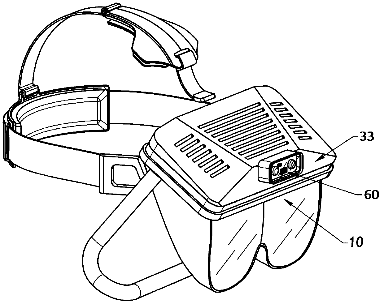
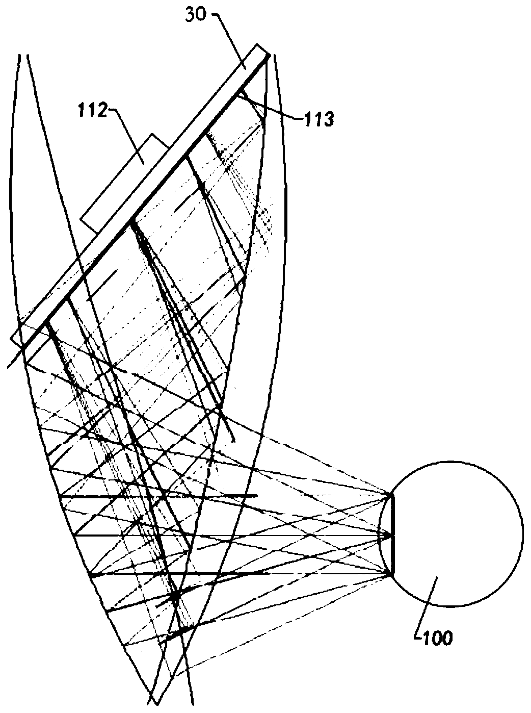
[0057] Such as figure 1 Shown is the overall appearance of the double free-form surface reflective AR glasses, 33 in the figure is the shell of the AR glasses, 10 is the first free-form surface lens, and 60 is the gesture recognition device connected to the main board. figure 2 It is a side view sectional view of an optical module of double free-form surface reflective AR glasses, and the optical module is composed of at least one display / projector, a second free-form surface lens, and a first free-form surface lens.

[0058] Such as Figure 2 to Figure 3A / B shows, figure 2 The middle is the principle diagram of the light projected by the display screen / device 113 (which may first pass through an intermediate optical element, such as a plano-convex lens, etc.), and then projected into the eyeball 100 after secondary reflection by the second free-form surface lens and the first free-form surface lens. 30 among the figure is main board, and 112 is the components and parts ...

Embodiment 2

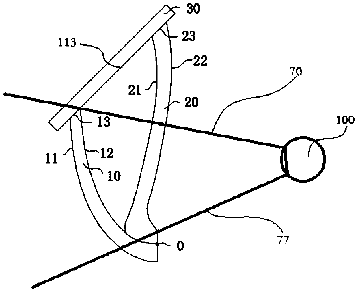
[0060] On the basis of the above examples, if Figure 4 to Figure 5A / B shows, such as Figure 4 As shown, it is a principle diagram of projecting the light projected by the splicing screen into the eyeball 100 after being reflected twice by the second free-form surface lens and the first free-form surface lens. again Figure 5A As shown, the two display screens 113 are spliced ​​in a stepped parallel dislocation arrangement, and in the figure, the eyeball 100 and the optical module (the two display screens 113 form an optical module with the second free-form surface lens 20 and the first free-form surface lens 10 respectively) The line connecting the upper junction point (approximately at position 13) is the uppermost range line of the longitudinal FOV, called the longitudinal FOV upper boundary extension line 70, the eyeball 100 and the optical module (two display screens 113 are respectively connected to the second free-form surface) The line connecting the lower junction ...

Embodiment 3

[0062] On the basis of Example 2, such as Figure 6A / B shows, Figure 6A As shown, the three display screens 113 are spliced ​​in a stepped parallel dislocation arrangement, in which the eyeball 100 and the optical module (the three display screens 113 form an optical module with the second free-form surface lens 20 and the first free-form surface lens 10 respectively) The line connecting the upper junction point (approximately at position 13) is the uppermost range line of the longitudinal FOV, which is called the upper boundary extension line 70 of the longitudinal FOV. The line connecting the lower intersection point (approximately at 0) of the lens 20 and the first free-form surface lens 10 is the lowermost range line of the longitudinal FOV, called the longitudinal FOV lower boundary extension line 77. same as Figure 6BAs shown, the position of the micro camera 200 is just above the extension line 70 of the upper boundary of the longitudinal FOV. From the user's pers...


PUM


Abstract

The invention discloses a screen projection device of double-free-form-surface reflection type AR glasses. The system comprises at least one display / projector and at least one optical device, a real image is constructed through the optical device, a virtual image is constructed after being projected in the optical device through the display / projector, the real image and the virtual image appear inthe same field of view in a combined manner, a micro camera is used for acquiring the real image and the virtual image in the same field of view at the same time and transmitting the image information to external display equipment in a wired or wireless communication connection manner. When a user wears the AR glasses, live broadcasting, rebroadcasting or recorded broadcasting under the real usecondition at the first visual angle can be realized, a played interactive picture of a user and the virtual display object is more real and credible, and phenomena of visual angle difference and spacedistance difference are avoided.

Description

technical field [0001] The present invention relates to a head-mounted display device, and more specifically, to a near-eye see-through head-mounted display optical system and a screen projection device for a camera system of an AR display device. Background technique [0002] Since the emergence of computer-generated image technology and the development of overlay technology with the real world, AR (augmented reality, augmented reality) and VR (virtual reality, virtual reality) have changed the traditional way of perception and interaction. No longer just interacting with digital information, but perceiving and interacting with the entire society. With the continuous advancement of design concepts, manufacturing levels and micro-display technology, AR display devices are entering various fields, such as entertainment, simulation training, and medical fields. [0003] The head-mounted display in the existing technology is only used by one person. To let more people know the...

Claims


Application Information

Patent Timeline
Patent Type & Authority Applications(China)
IPC IPC(8): G02B27/01H04N7/18
CPCG02B27/0172G02B2027/0138H04N7/18
Inventor 房晓俊
Owner TAPUYIHAI SHANGHAI INTELLIGENT TECH CO LTD
Learn More