Display device
A technology of a display device and a display screen, applied in the field of photography, can solve the problems of cross-light between the camera lens and the display screen, narrowing of the volume space, etc., to avoid halo, solve the cross-light, and improve product quality and market competitiveness.
- Summary
- Abstract
- Description
- Claims
- Application Information
AI Technical Summary
Problems solved by technology
Method used
Image
Examples
no. 1 example
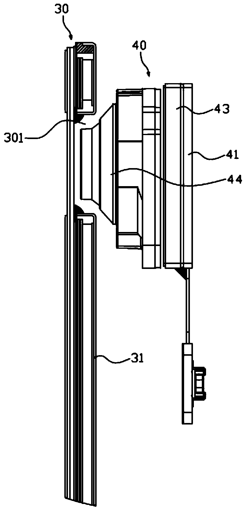
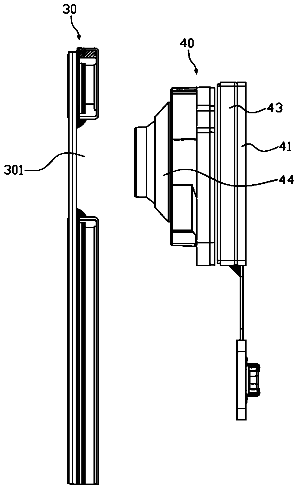
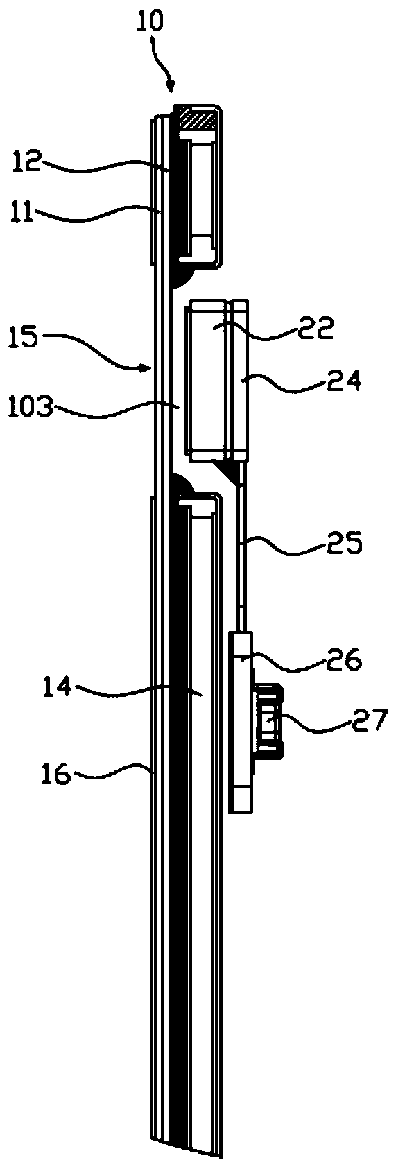
[0032] image 3 is a partial schematic view of the display device according to the first embodiment of the present invention, such as image 3 As shown, the display device includes a display screen 10 and a camera module 20; the display screen 10 is, for example, a liquid crystal display 10; the camera module 20 is used for taking pictures and taking pictures. In this embodiment, the display device is a mobile terminal, such as a mobile phone, a tablet computer, a notebook computer, a palmtop computer, and the like.
[0033] further, Figure 4 yes image 3 The partially enlarged schematic diagram of the display screen shown, such as image 3 with Figure 4 As shown, the display screen 10 includes a first substrate 11 and a second substrate 12 that are oppositely arranged, a first focusing lens 113 is formed on a part of the first substrate 11, a second focusing lens 123 is formed on a part of the second substrate 12, and the first focusing lens 123 is formed on a part of t...
no. 2 example
[0048] Figure 6 It is a partial enlarged schematic diagram of the display screen of the second embodiment of the present invention, as Figure 6 As shown, the display device of this embodiment is substantially the same as that of the first embodiment, except that the partial structure of the display screen 10 is different.
[0049] Specifically, the first substrate 11 includes a first bottom plate 112 and a color filter layer 114 disposed on the first bottom plate 112. The color filter layer 114 is provided with a first opening 101 exposing the first focusing lens 113. The first focusing The lens 113 is integrally formed with the first bottom plate 112 . The first focusing lens 113 has a first surface 11a and a second surface 11b, the second surface 11b is close to the second focusing lens 123, and the second surface 11b is provided with a first optical ion film 115 for improving light transmission efficiency. The material of the first optical ion film 115 is CaF 2 , but n...
no. 3 example
[0054] Figure 7 It is a partially enlarged schematic diagram of the display screen of the third embodiment of the present invention, as shown in Figure 7 As shown, the display device of this embodiment is substantially the same as that of the first embodiment, except that the partial structure of the display screen 10 is different.
[0055] Specifically, the second substrate 12 includes a second bottom plate 122 and a control circuit layer 124 disposed on the second bottom plate 122. The control circuit layer 124 is provided with a second opening 102 exposing the second focusing lens 123. The second focusing lens 123 It is integrally formed with the second bottom plate 122 . The second focusing lens 123 has a third surface 12a and a fourth surface 12b, the third surface 12a is close to the first focusing lens 113, and a second optical ion film 125 is provided on the third surface 12a for improving light transmission efficiency. The material of the second optical ion membra...
PUM
 Abstract
Description
Claims
Application Information
 - R&D
- Intellectual Property
- Life Sciences
- Materials
- Tech Scout
- Unparalleled Data Quality
- Higher Quality Content
- 60% Fewer Hallucinations
Browse by: Latest US Patents, China's latest patents, Technical Efficacy Thesaurus, Application Domain, Technology Topic, Popular Technical Reports.
© 2025 PatSnap. All rights reserved.Legal|Privacy policy|Modern Slavery Act Transparency Statement|Sitemap|About US| Contact US: help@patsnap.com


